AMD
P R E L I M I N A R Y
42
Am79C930
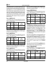
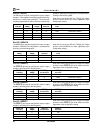
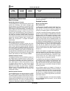
LLOCKE/ LLOCKE/
PCMCIA LLOCKEN SA15 Pin SA15 Pin
Pin Value TCR14[6] Direction Value
0 X I NA (SA15 input function)
10I NA
1 1 O TIR11[4]
FUNCTIONAL DESCRIPTION
Basic Functions
System Bus Interface Function
The Am79C930 device is designed with a choice of two
system bus interfaces. The system designer may
choose between the PCMCIA bus and the ISA (IEEE
P996) bus with support for Plug and Play. Both inter-
faces support an 8-bit wide data bus. The system inter-
face is used by the host driver software to initialize the
Am79C930 device through a series of slave I/O ac-
cesses to the Am79C930 device. Device operation is
monitored by accessing Am79C930 registers through
the system bus interface. Network data is transferred
to/from the driver through slave memory accesses at the
system bus interface. Network data is stored in the
SRAM that accompanies a complete Am79C930-
based design.
Memory Bus Interface Function
The Am79C930 device contains a memory bus inter-
face, which is used by the Am79C930 device to gain ac-
cess to Flash memory for fetching 80188 instructions
and to gain access to SRAM for fetching and storing
driver commands, network data, and for temporary vari-
able storage. Software driver transfers of network data
are passed to the Am79C930 device through the system
bus interface and will be automatically rerouted to the
memory bus interface in order to reach the SRAM.
Software Interface Function
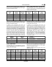
The software interface to the Am79C930 consists of a
set of 256K memory locations and 16 (or 40) I/O loca-
tions. 128K of these memory locations map directly to
an SRAM that is attached to the memory interface. An-
other 128K maps to a Flash memory device. Due to
overlapping address space as viewed by the 80188
embedded processor core, 128 bytes of the SRAM
space are not usable for driver function. Additional
registers exist in the Am79C930 device for use by
industry standard PCMCIA and ISA Plug and Play
configuration utilities.
Network Interface Function
The Am79C930 device can be connected to an IEEE
802.11 (draft) network via a flexible network interface.
The flexible network interface allows the user to define
much of the pin functionality in order to assist in accom-
modating the Am79C930 device to a number of different
network transceivers. Pin control is achieved through
Transceiver Attachment Interface (TAI) registers (TIR
and TCR). These registers are controlled through 80188
firmware instructions.
Detailed Functions
Block Level Description
Bus Interface Unit
The Bus Interface Unit (BIU) supports either of two com-
mon interfaces: PCMCIA and ISA (IEEE P996) with
Plug and Play. The choice of interface is determined
through a pin strapping option via the PCMCIA pin.
Two sets of command and status registers exist within
the BIU. One set of registers is labeled System Interface
Registers (SIR). The SIR registers are used to control
the general function of the device by providing various
resets and by allowing some direct communication be-
tween the host system and the embedded 80188. The
SIR registers are visible to the system interface, but are
not visible to the 80188 embedded core. The second set
of BIU registers is the MAC Interface Registers (MIR).
The MIR registers are visible to the 80188 embedded
core, but are not visible from the system interface.
Some commands within each register set allow indirect
communication between the system interface and the
80188 core.
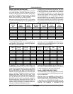
Another set of registers is located in the Transceiver At-
tachment Interface Unit, the TIR registers. The TIR loca-
tions are visible through the BIU. These registers are
normally used by the 80188 core to control the Trans-
ceiver function; they are visible through the system
interface primarily for diagnostic purposes.
The PCMCIA Card Configuration Registers and the set
of ISA Plug and Play registers are implemented in the
BIU. PCMCIA Card Information Structure and the ISA
Plug and Play Resource Data area are both mapped to
Flash space and are accessible through the system
interface of the BIU.
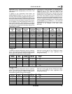
All Am79C930 registers are located in I/O space as
viewed from the system interface. There are no memory
resources located inside of the BIU unit, although there
are memory resources that are accessed through
the BIU. For a complete description of all resources
accessible inside of and through the BIU, see the Soft-
ware Access section.
For a complete description of all resources accessible
by the embedded 80188 processor, see the 80188
Firmware section.


