


AMD
P R E L I M I N A R Y
124
Am79C930
PCMCIA CCR Registers and PCMCIA
CIS Space
Two bytes of attribute memory space have been
used by the Am79C930 device for storage of two card
configuration registers. These two registers are found
at attribute memory locations 800h and 802h. The
Configuration Option Register is located at Attribute
memory location 800h and the Card Configuration
and Status Register is located at Attribute memory
location 802h.
Because the location of these registers is fixed at 800h
and 802 in attribute memory space, then the value of the
CCR Offset located in the TPCC_RADR field of the Con-
figuration Tuple
must
be equal to 800h.
PCMCIA Configuration Option Register
This register is used to configure the Am79C930 device
and to issue a soft reset to the Am79C930 device.
The PCMCIA Configuration Option Register is located
at the fixed attribute memory location 0802h. Therefore,
the information programmed into the CIS must give the
value 2K (=0800h) as the Card Configuration Registers
Base Address in the TPCC_RADR field of the Configu-
ration Tuple. The Configuration Option Register is lo-
cated at TPCC_RADR + 2.
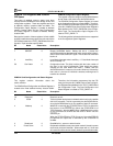
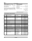
The following tables indicate the bits that are supported
in the Configuration Option Registers:
Bit Name Reset Value Description
7 SRESET 0 Resets Am79C930 device. Setting this bit to 1 places the
Am79C930 device into the reset state, which is equivalent to the as-
sertion of the PCMCIA RESET signal. This bit does not reset itself
back to 0.
6 LevelReq 0 Level Mode Interrupts when LevelReq = 1. Pulse Mode Interrupts
when LevelReq = 0.
5:0 Conf Index 0 Configuration Index. This field is written with the index number of
the entry in the card’s Configuration Table which the system
chooses for this card. When Conf Index = “00000,” then the
Am79C930 device is in memory only mode. When any of these five
bits is set to 1, then the I/O interface is enabled, meaning that I/O
transfers are allowed.
PCMCIA Card Configuration and Status Register
This register contains information about the
card’s condition.
The PCMCIA Card Configuration and Status Register is
located at the fixed attribute memory location 0802h.
Therefore, the information programmed into the CIS
must give the value 2K (=0800h) as the Card Configura-
tion Registers Base Address in the TPCC_RADR field of
the Configuration Tuple. The Card Configuration and
Status Register is located at TPCC_RADR + 2.
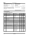
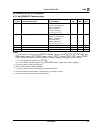
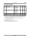
Bit Name Reset Value Description
7:6 Reserved – Read only as a 0.
5 IOIS8 0 This bit is written by the host to indicate that the host is only capable
of 8-bit I/O accesses. This bit is ignored by the Am79C930 device,
since the Am79C930 device is only capable of 8-bit I/O accesses.
4 Wakeup 0 WAKEUP is used with the STSCHGFN bit of TCR15 to determine
the function of the STSCHG pin. When the STSCHGFN bit of
TCR15 is set to 1, then the WAKEUP bit is NANDed with the value
of the STSCHGD bit of MIR8 and the result is driven onto the
STSCHG pin.
When the STSCHGFN bit of TCR15 is set to 0, then the STSCHG
pin becomes an output that is controlled by the STSCHGD bit
of MIR8.
3 Read-back 0 Read/Write bit – serves no other function.
2 Power Down 0 Requests the 80188 to enter power down mode. If already in power
down mode, this bit will indicate 1. When written with a 1, value read
will remain 0 until the device actually enters the power down mode.