AMD
P R E L I M I N A R Y
66
Am79C930
The SRAM is intended to serve as a shared memory re-
source between the driver operating through the system
interface and the 80188 core operating through the
Am79C930 memory interface bus. Even though SRAM
memory locations 0 0400h through 0 043Fh are acces-
sible from the system interface, these locations cannot
be used for driver-firmware shared memory functions,
since they are inaccessible from the 80188 core.
ISA Plug and Play I/O Resources — The Am79C930
device occupies 16 bytes of I/O space. The 40-byte I/O
option is not available in the ISA Plug and Play mode of
operation. The EIOW bit (bit 2 of the BSS register
(SIR1)) will be forced to 0 when the Am79C930 device
has been placed into ISA Plug and Play mode. The I/O
space of the Am79C930 device contains the General
Configuration Register, the Bank Switching Select Reg-
ister, and the set of 32 TIR registers. Additionally, all
Am79C930 resources are accessible through I/O ac-
cesses, i.e., all
memory
structures are accessible
through the Local Memory Address and I/O Data
Ports (SIR2,3,4,5,6,7).
The Local Memory Address port plus SIR1[5:3] function
together as a pointer to the memory resources of the
Am79C930 device. SIR1[5] determines the device se-
lected (SRAM or Flash) and SIR1[4:3], and LMA[14:0]
supply the address to the selected device whenever the
I/O Data Port is read or written. Whenever any of the I/O
Data Ports is accessed, then the Local Memory Address
Port value is automatically incremented by a value of 1.
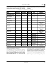
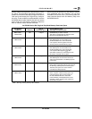
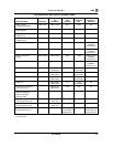
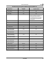
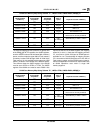
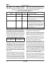
The next table indicates the mapping of all I/O resources
that are accessible through the Am79C930 ISA
system interface.
Note that some resources are physically located within
the BIU, while others are located in the TAI, and still oth-
ers exist as external Flash and SRAM. Also note that
additional registers for ISA Plug and Play exist in the BIU
and are indirectly accessed through the Plug and Play
ADDRESS, WRITE_DATA, and READ_DATA ports.
All resources are 1 byte in width.
When accessing Am79C930 I/O resources through ISA
I/O cycle accesses, the upper 8 bits of the ISA system
address will be ignored. Only the lower 16 bits of
address will be used to check for a match of the address
range assigned to the Am79C930 device by the Plug
and Play configuration program (i.e., the I/O Base Ad-
dress = IOBA). (The Plug and Play configuration pro-
gram will have written an I/O base address value into the
I/O Base Address registers (Plug and Play ports 60h
and 61h) following system boot up and auto-configura-
tion.) The ISA Plug and Play I/O base address
must
be
aligned to a 16-byte boundary in I/O space. This align-
ment requirement should be included in the Resource
Data I/O Port Descriptor Base Alignment field that is
programmed into the Flash device and read by the Plug
and Play configuration utility. These conditions
must
be
satisfied for proper operation.


