USER’S GUIDE
Appendix–8
INTERFACE SPECIFICATIONS
Bi-directional Parallel Interface
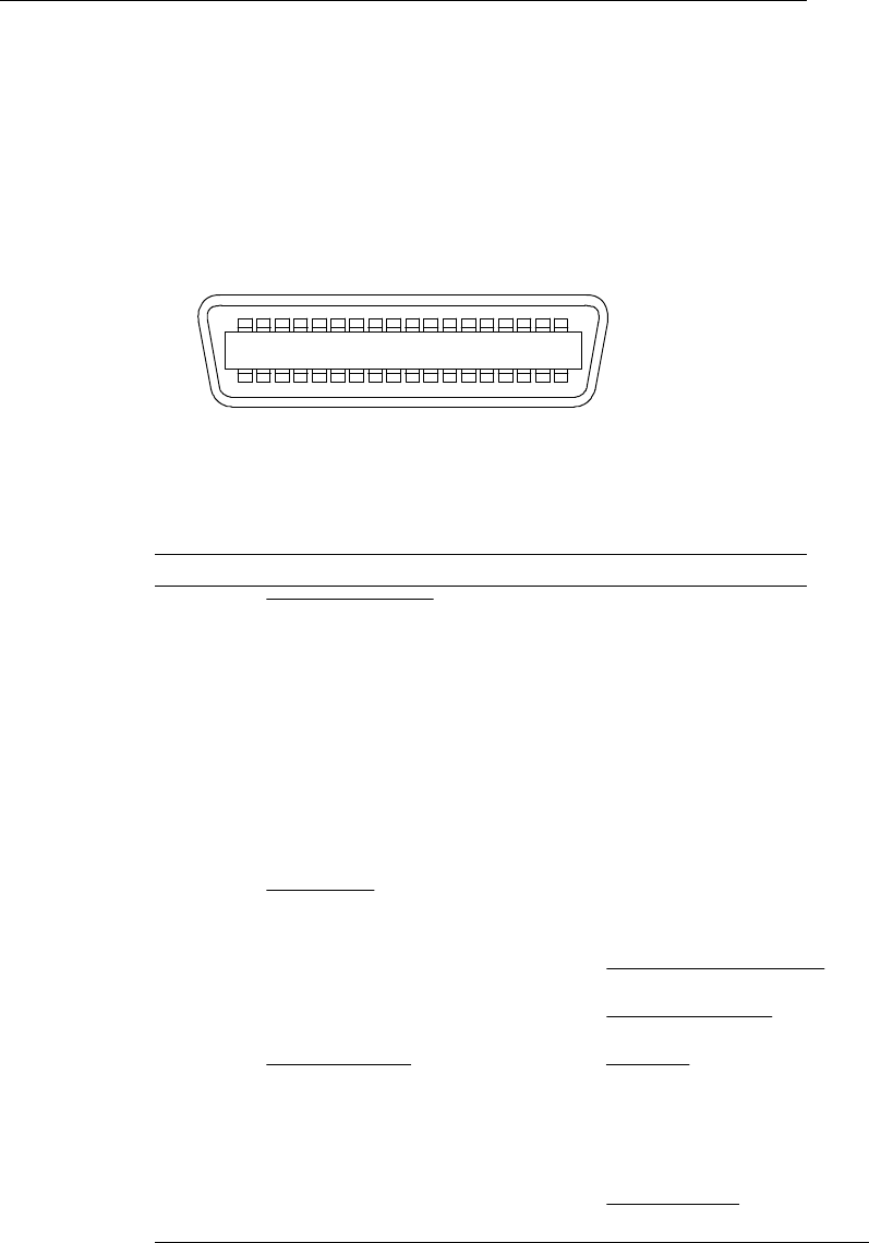
Interface Connector
A shielded cable with the following pin assignment should be
used. Most existing parallel cables support bi-directional
communication, but some might have incompatible pin
assignments.
18 15 12 9 6 3 1
36 33 30 27 24 21 19
Fig. A-1 Parallel Interface Connector
Pin Assignment
Pin No.
Signal Pin No. Signal
1 DATA STROBE 19 Twisted pair ground
2
DATA 0 20 Twisted pair ground
3
DATA 1 21 Twisted pair ground
4
DATA 2 22 Twisted pair ground
5
DATA 3 23 Twisted pair ground
6
DATA 4 24 Twisted pair ground
7
DATA 5 25 Twisted pair ground
8
DATA 6 26 Twisted pair ground
9
DATA 7 27 Twisted pair ground
10 ACKNLG
28 Twisted pair ground
11
BUSY 29 Twisted pair ground
12
PE 30 INPUT PRIME RET
13 SLCT 31 INPUT PRIME
14 AUTO FEED 32 FAULT
15 N.C. 33 N.C.
16
0V 34 N.C.
17
0V 35 N.C.
18
+5V 36 SELECT IN


