


III - 1
CHAPTER III ELECTRICAL SYSTEM
Electric signal levels are expressed by ”High” (approximate the supply voltage) or ”Low”
(approximate 0V). Signals with hyphen or slash, such as -FSRD or FSRD/, are low-active and
signals without hyphen or slash, such as FSRD, are high-active signals.
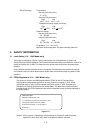
1. MAIN PCB
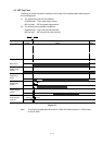
1.1 Outline
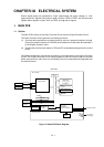
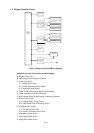
The Main PCB consists of the Video Controller Circuit and the Engine Controller Circuit.
The Video Controller Circuit performs the following functions.
(1) Converts data received from an external device, such as a personal computer, through
Centronics parallel interface or RS-232C serial interface into video data and transfers it
to the Engine controller circuit.
(2) Displays the current printer status in LED and LCD, and enables settings from the control
panel.
The operation sequence of the printer controlled by a microprocessor in the Engine Controller
Circuit. The Engine Controller Circuit outputs signals to drive the various loads on the laser
diode, scanner motor, main motor, etc. according to the print commands and image data from
the external device.
FONT
CARTRIDGE
IC CARD
(PCMCIA)
MIO BOARD
Regurator
+24V
PC
PC
CDCC (bolse) IF
RS-232C IF
ASIC
HG51CS265FD
Video controller
Engine controller
Engine CPU
M38063
+24V
+5V
GND
CONTROL PANEL
Low-voltage
Power Supply
Gate Array
µPD65632GC
(IO PORT. ENGINE)
MASK ROM
16M mask 2 4MB
8M mask 2 2MB
DRAM
4M 4 2MB
DRAM (SIMM 2 Slots)
64MBmax.
EEPROM
24CO4 4Kbit
Main CPU
79R3041
Main PCB
MIO RELAY
(CONNECTOR)
PCB
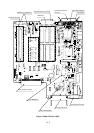
Figure 3.1 Main PCB Block Diagram