


III - 11
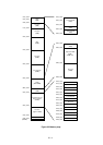
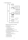
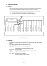
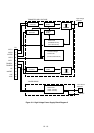
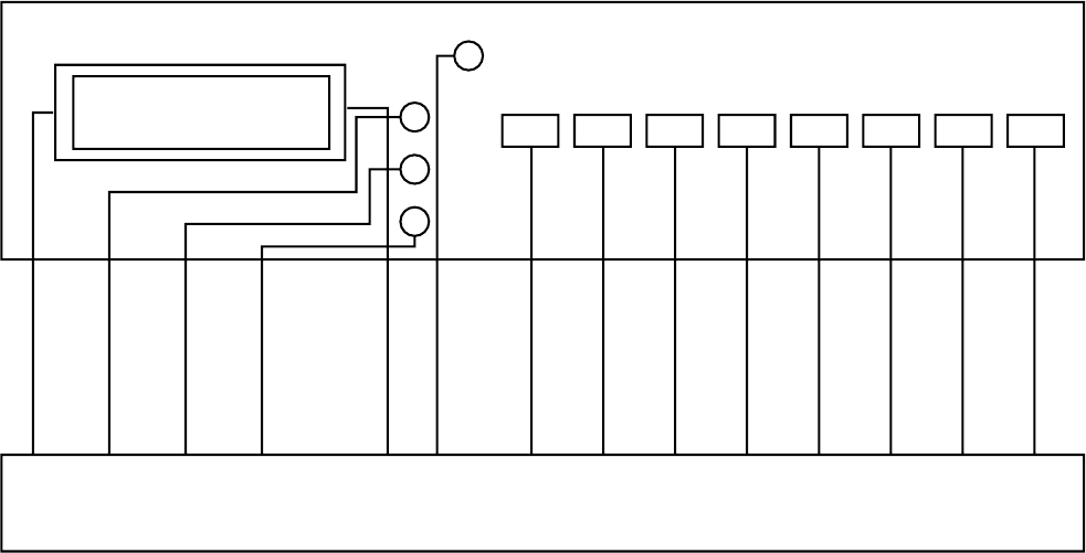
LCD
LED1
LED3
LED4
LED2
SW8 SW7 SW6 SW5 SW4 SW3 SW2 SW1
PAD4-PAD7
LED2 (READY)
LED3 (DATA)
LED4 (ALARM)
LCDE, LCDRS
LED1 (ONLINE)
SW8 (SEL)
SW7 (MODE)
SW6 (FONT)
SW5 (
FORM FEED
)
SW4 (SET)
SW3 (CONTINUE)
SW2 (DOWN)
SW1 (UP)
Main PCB
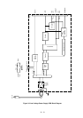
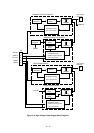
Figure 3.8 Display Circuit
3.2 Operation
Indicators on the control panel (LED lamps and LCD) are controlled by the video controller
circuit.
All the switch signals are input to the video controller circuit.
Signals Descriptions:
LED1 - LED4 On-off control for the respective LED lamps.
Illuminating when Low and extinguished when High.
PAD4 - PAD7 LCD control signal.
LCDRS A signal to distinguish PAD4 - PAD7 into command and data.
LCDE A signal to start the operation.
SW1 - SW8 Input signals from the switches.
Going Low when each switch is pressed.
3. DISPLAY CIRCUIT
3.1 Outline
The control panel of this printer has four LED lamps, one LCD display, and eight switches.
The control panel is connected to the Main PCB and its functions are as follows:
(1) The LCD shows the printer status and error message in alpha-numeric characters.
(2) The LED lamps indicate the operating conditions of the printer.
(3) The printing mode and LCD brightness can be changed by switches.