


III - 7
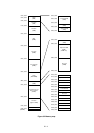
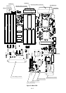
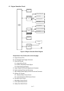
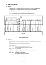
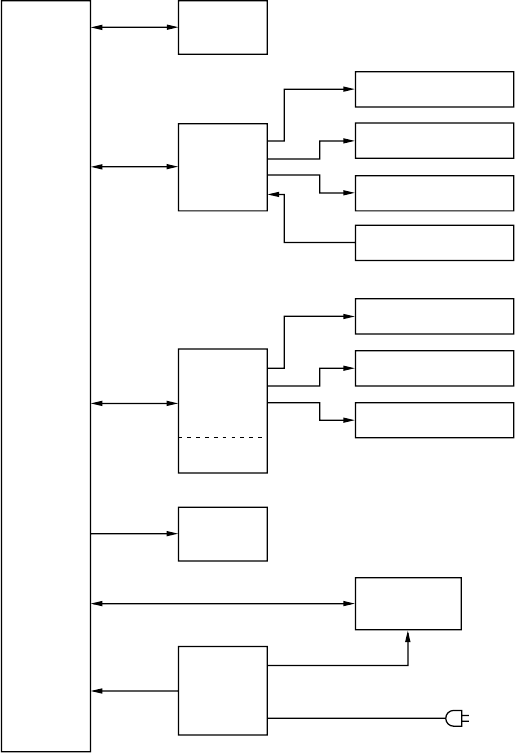
1.3 Engine Controller Circuit
A. Engine Control CPU
B. Low-Voltage Power Supply Connector
C. Fuser Unit Control
C-1. Heater Drive Circuit
C-2. Heater Temperature Input Signal
C-3. Paper Eject Input Signal
D. Paper Feeder PCB Control Signals and Connector
E. Option Interface Circuit and Connector
F. High-Voltage Power Supply Control Circuit and Connector
G. Scanner Unit Control
G-1. Scanner Motor Control Circuit
G-2. Laser Diode Drive PCB Control Circuit
H. Fan Motor Drive Circuit
I. Main Motor Control Circuit
J. Cover Open Detect Circuit
K. Safety Door Switch Circuit
Components in the Circuit (refer to the next page)
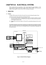
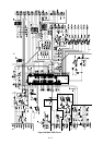
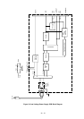
Engine
Controller
Circuit
Primary charging roller
MP Tray Pick-up Solenoid
Scanner Unit
High-Voltage
Power Supply
Assy
Paper Feeder
PCB
Detectors
Main Motor
Low-Voltage
Power Supply
Assy
Pick-up Motor
Fixing Unit
Transfer roller
Developing cylinder
Toner sensor
Pick-up Solenoid
Figure 3.5 Engine Controller Block Diagram