


ii
CHAPTER III ELECTRICAL SYSTEM
1. MAIN PCB........................................................................................................................ III-1
1.1 Outline.................................................................................................................... III-1
1.2 Video Controller Circuit .......................................................................................... III-2
1.3 Engine Controller Circuit ........................................................................................ III-7
2. PAPER FEED DRIVE CIRCUIT ....................................................................................... III-9
3. DISPLAY CIRCUIT .........................................................................................................III-11
3.1 Outline..................................................................................................................III-11
3.2 Operation .............................................................................................................III-11
4. LOW-VOLTAGE POWER SUPPLY ASSY....................................................................... III-12
4.1 Outline..................................................................................................................III-12
4.2 Protection Functions ............................................................................................III-12
5. HIGH-VOLTAGE POWER SUPPLY ASSY...................................................................... III-14
5.1 Outline..................................................................................................................III-14
5.2 Operation of the Components of the High-Voltage Power Supply Assy ...............III-14
CHAPTER IV MECHANICAL SYSTEM
PRINTER DISASSEMBLING PROCEDURE
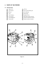
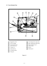
PRINTER BODY
1.1 Configuration.......................................................................................................... IV-3
1.2 Toner Cartridge Lid ................................................................................................ IV-3
1.3 Side Cover L .......................................................................................................... IV-3
1.4 Font Cover Assy..................................................................................................... IV-4
1.5 Upper Cover Assy, Rear Cover Assy...................................................................... IV-4
1.5.1 Upper cover assy, rear cover assy ........................................................... IV-4
1.5.2 Changeover guide, jam remove cover......................................................IV-5
1.6 Side Cover R .......................................................................................................... IV-5
1.7 DC Fan Motor ......................................................................................................... IV-6
1.8 Main PCB ............................................................................................................... IV-6
1.9 Control Panel Unit .................................................................................................. IV-8
1.10 Scanner Unit .......................................................................................................... IV-9
1.11 Cartridge Stopper Assy .......................................................................................... IV-9
1.12 Paper Feed Chassis Unit .....................................................................................IV-10
1.13 Separation Pad Assy ............................................................................................ IV-11
1.14 MP PE Sub Actuator ............................................................................................ IV-12
1.15 P Feed /Size-SW PCB Assy................................................................................. IV-12
1.16 Side-Switch Spring ............................................................................................... IV-12
1.17 Regist Sensor Actuator ........................................................................................ IV-13
1.18 MP Paper Detection Actuator ............................................................................... IV-13
1.19 PE Sensor Actuator MP ....................................................................................... IV-13
1.20 Tray Sensor Holder .............................................................................................. IV-14
1.21 Roller Holder ........................................................................................................ IV-14
1.22 Paper Pick-up Roller Assy, Bearing ...................................................................... IV-15
1.23 Paper Pick-up Solenoid ........................................................................................ IV-16
1.24 Paper Feed Motor Assy ........................................................................................ IV-16
1.25 MP Tray Cover ...................................................................................................... IV-17
1.26 MP Tray Assy ....................................................................................................... IV-17
1.27 Paper Path Separation Plate, Paper Path Separation Film .................................. IV-18
1.28 Latch .................................................................................................................... IV-19
1.29 Fixing Unit (for both 120V and 230V, the only difference is the halogen heater). IV-19
1.30 Transfer Unit ......................................................................................................... IV-22