


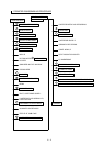
III - 14
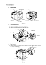
5. HIGH-VOLTAGE POWER SUPPLY ASSY
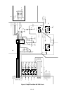
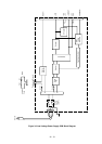
5.1 Outline
The High-Voltage Power Supply Assy supplies the high-voltage for the charging roller, the
developer cylinder and the transfer roller according to the engine CPU’s control signals.
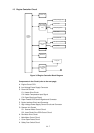
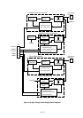
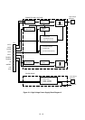
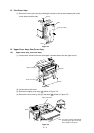
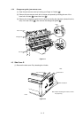
The block diagrams are shown Fig 3.10 and 3.11.
5.2 Operation of the Components of the High-Voltage Power Supply Assy
(1) Primary charging
When input signal/HV1AC gets the Low level, the primary high-voltage AC is applied to the
primary charging roller. And when input signal/HV1DC gets the Low level, the primary high-
voltage DC is applied to the primary charging roller. The primary high-voltage DC changes with
developer bias DC according to values of the input signal DNSTY which is for print density
adjustment.
(2) Developer bias
When input signal/DBAC gets the Low level, the developer bias AC is applied to the developer
cylinder. And when input signal/DBDC gets the Low level, the developer bias DC is applied to
the developer cylinder. The developer bias DC changes according to values of the input signal
DNSTY which is for print density adjustment, like the primary high-voltage DC.
(3) Transfer charging
Transfer bias is controlled by the input signals HVT1 - 4 and HVTFB. When the input signal/
HVT1 gets the Low level, negative high-voltage is applied to the transfer roller. When the input
signal/HVT2 gets the Low level, positive high-voltage is applied to the transfer roller. When the
input signal/HVT3 gets the Low level, positive high-voltage about 1100 times that of the input
signal HVT4 is applied to the transfer roller. The input signal HVTFB has voltage about 1/1100
times the positive voltage generated on the transfer roller. Once the engine CPU is informed of
this voltage, the bias applied to the transfer roller can be known.
Note: The HVT2 signal generates high-voltage irrespective of the HVT4 signal.
(4) Toner sensing
Voltage levels of the input signals TONER1 and TONER2 allow the engine CPU to check if the
cartridge is set or not and if toner is empty. The TONER1 carries the voltage generated at the
toner sensor and the TONER2 carries the developing bias output value.