IV - 3
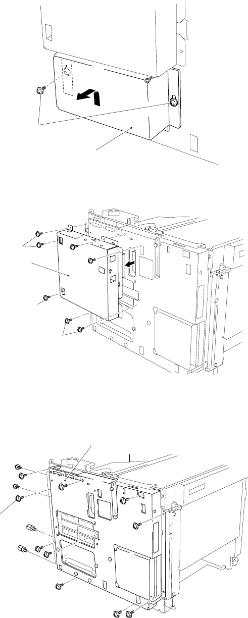
Figure 4.3
1.8 Main PCB
(1) Remove the SIMM replace lid.
Screws (yellow)
SIMM replace lid
(2) Remove the MIO box.
Figure 4.4
(3) Remove the PCB holder by loosening PCB holder fixing screws, 2 centronics connector
screws and 2 RS-232C connector screws.
PCB holder
Screws
Figure 4.5
MIO box
Screws
Screws
Screws


