


II - 1
CHAPTER II THEORY OF OPERATION
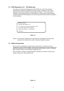
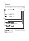
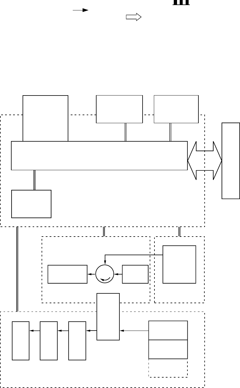
This chapter describes the printer functions, the relationship between the electrical systems and
mechanical systems, and the timing of operations. Striped conduits ( ) indicate mechanical
linkages; solid thin arrows ( ) appearing with a signal name indicate the transmission of
single control signals and outlined thick arrows ( ) indicate the transmission of groups of
signals.
1. BASIC OPERATIONS
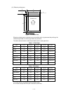
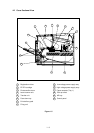
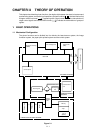
1.1 Mechanical Configuration
The printer functions can be divided into four blocks: the laser/scanner system, the image
formation system, the paper pick-up/feed system and the control system.
Figure 2.1
Expansion memory
(SIMM)
Font cartridge/card
Optional I/O
(MIO)
External Device
Control panel
IMAGE FORMATION SYSTEM
Cleaning unit
Photosensitive drum
Developing
unit
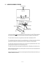
Laser/scanner
unit
LASER/SCANNER
SYSTEM
Transfer
separation
unit
Delivery rollers
Fixing unit
Feeder
Tray 1
Tray 2
(Option)
MP tray
Main PCB
CONTROL SYSTEM
PAPER PICK-UP/FEED SYSTEM