


Chapter 3: Installation
3-8 8H02-16 User’s Guide
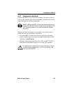
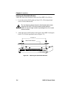
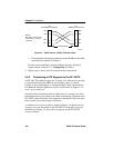
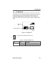
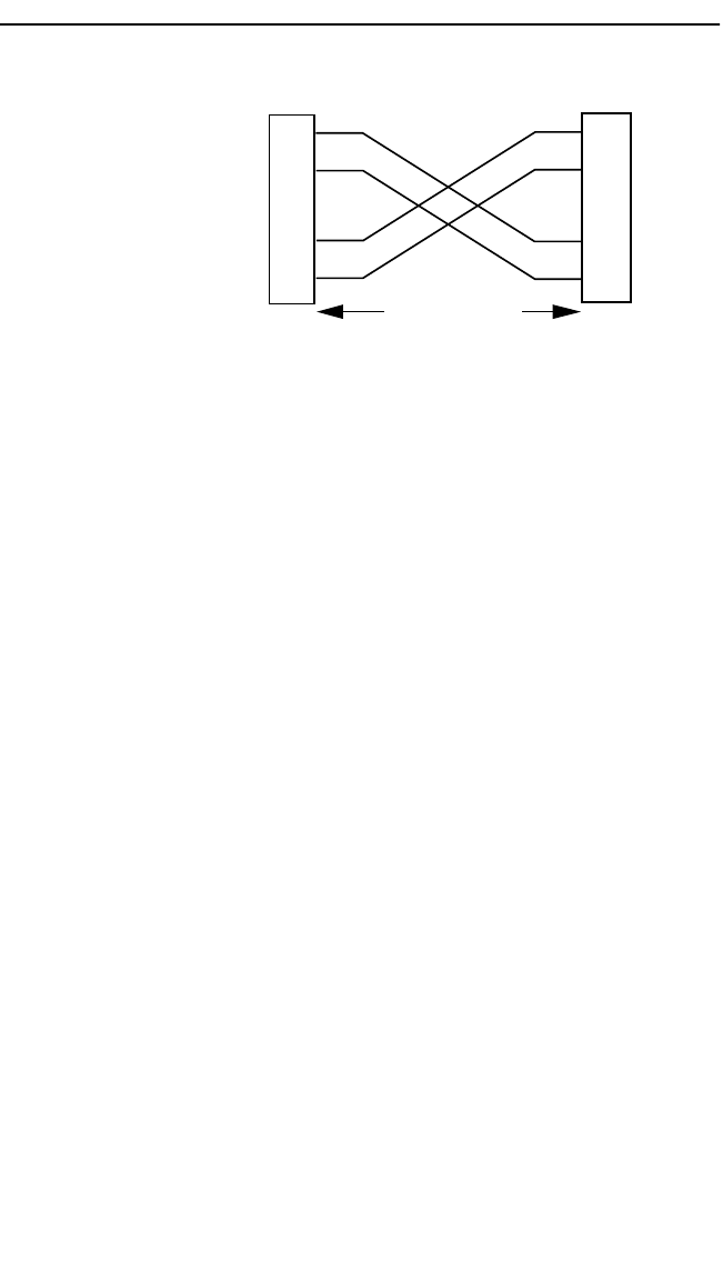
Figure 3-6 Cable Pinouts - (RJ45) Crossover Cable
c. Check that the twisted pair connection meets the dB loss and cable
specifications outlined in Chapter 2.
If a link is not established, contact Cabletron Systems Technical
Support. Refer to Section 1.7, Getting Help, for details.
4. Repeat step 2, above, until all connections have been made.
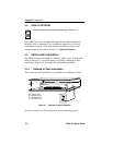
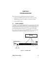
3.5.2 Connecting a UTP Segment to the FE-100TX
An FE-100-TX installed in port slot 15 and/or 16 is often used to provide
a connection between the 8H02-16 and a bridge, router, or switch.
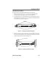
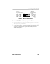
Usually, in this configuration, a “straight-through” cable is used and the
Fast Ethernet Interface Module crossover switch shown in Figure 3-7 is
set to “not crossed over.”
Normally, when connecting devices to like devices, crossing over of the
transmit and receive pairs must occur. Before connecting a segment to the
FE-100TX, check each end of the segment to determine if the wires have
been crossed over for the proper connection.
A schematic of a crossover cable is shown in Figure 3-6. If the wires do
not cross over, use the switch on the FE-100TX to internally cross over
the RJ45 port. Figure 3-7 shows how to properly set the FE-100TX
crossover switch.
TX+
TX–
RX+
RX– 2
1
3
6
TO
10BASE-T Device Port
TX+
TX–
2
1
3
6
NOTE:
RX+/RX– and TX+/TX–
must share a common
color pair.
TO
SmartSwitch RJ45 Port
1574-30
RJ45 to RJ45
RX+
RX–