


www.axxessid.com
Installation & User Guide
AX200 Installation & User Guide – July 2007
115
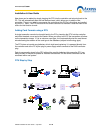
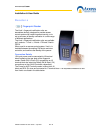
Proximity Readers
Honeywell proximity readers have been designed to be installed
for use with access control systems. The following instructions
outline the connections between the reader and the AX200 access
control system as well as the software configurations that need to
be carried out in order to make the system ready to operate.
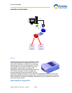
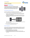
How to connect the reader to the host
The reader is supplied with an 18-inch pigtail, having a 6-conductor
cable. To connect the reader to the AX200 system, perform the following steps:
1. If there is a connector on the end of the cable (used during manufacture for testing
purposes), cut it off. Prepare the reader cable by cutting the cable jacket back 1.25
inches and strip the wires 0.5 inch.
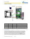
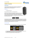
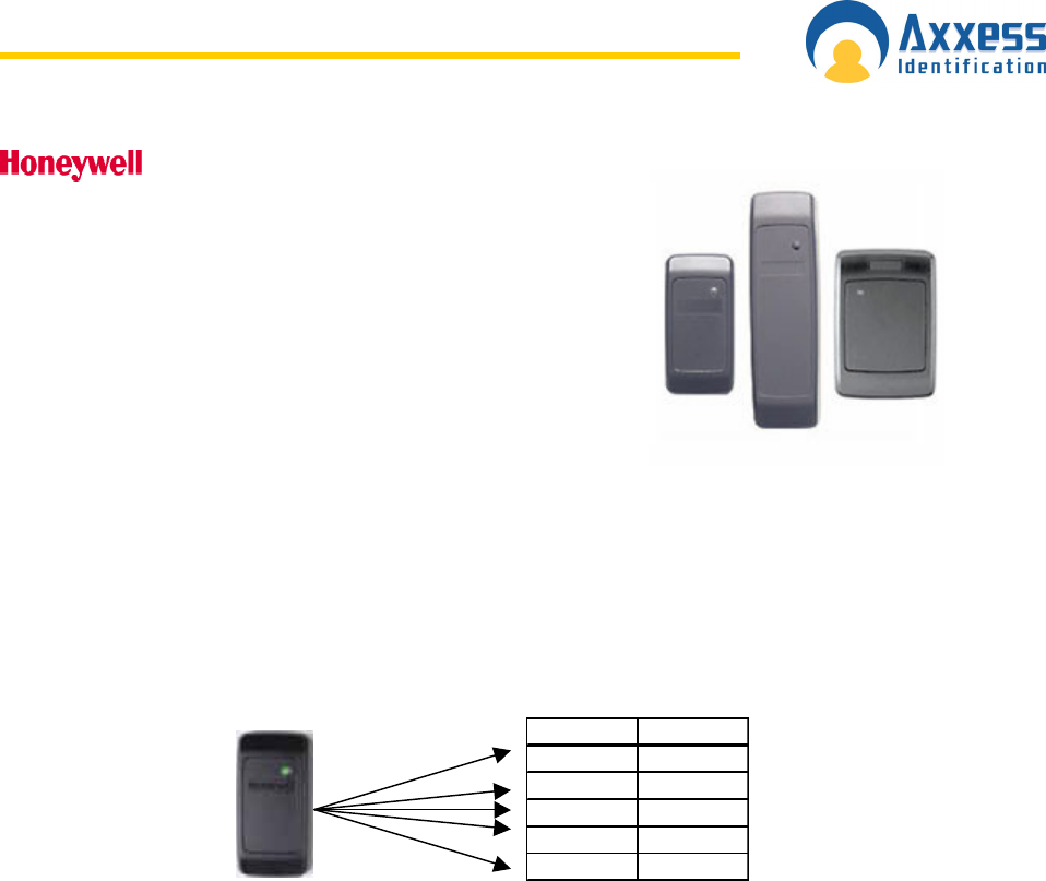
2. The reader is connected directly to the AX100 controller. The table below shows the
connections on the AX100 controller and the corresponding wires on the Honeywell
proximity reader.
Colour AX100
Red 12V
Black 0V
White D1
Green D0
Brown LED
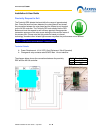
When using a separate power supply for the reader, power supply and the AX100 must
have a common ground.
3. Do not connect the Tamper (purple) lead to the AX100.
4. Trim and cover all conductors that are not used.
Software Configuration
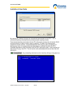
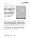
Once the reader & the AX100 controller have been connected to the AX200 unit you should be
able to see it on the controllers menu on the right hand side of the main screen. In order to
program a valid card with the ability to have access through a Honeywell proximity reader you
need to choose the correct format.
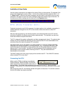
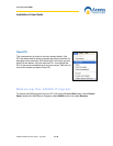
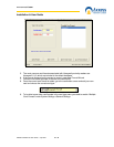
1. On the main screen click on the Format & Statistics.
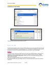
2. Under the Card Matching tab press “Select Reader”
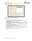
3. Choose the appropriate reader from the list and present the card to the reader
4. The software will automatically display the card number, Facility Code and the possible
card formats.