


www.axxessid.com
Installation & User Guide
AX200 Installation & User Guide – July 2007
15
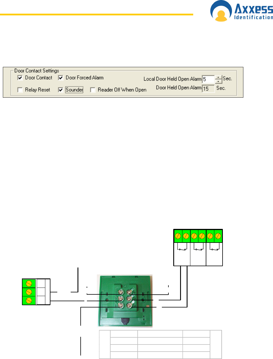
Door forced / held open alarm settings can be accessed through Main Screen • Access Point •
(Enable) Door Contact.
For more information about these settings please refer to Access Point Configuration • Access
Point Settings on this manual.
Note: Relay No.3 generates a 1 second pulse through the Access Granted connection block,
located at the top of AX200 board. The connection is normally closed and the pulse is generated
once the access is granted through either door.
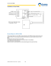
Diagrams on the following pages illustrate the connections between the AX200 components.
Please note that if you are installing a brand new unit, the Fire Alarm, Break glass & PSU
Monitoring links will not be activated until the first time they are used.
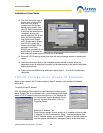
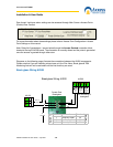
Break glass Wiring AX200
Bre akglass
Door 1
OUT
Breakglass
Door 2
IN
PSU
Monitoring
Volt Free
NC
CNC2A 2A3A 3A
2A
3A
3
to lock
2
AX200
Power In
+12vDC
Double Pole
Breakglass
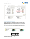
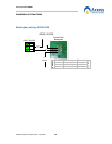
Breakglass Wiring AX200
Terminal Function Terminal
1 Normally Open 1A
2 Common 2A
3 Normally Closed 3A
Switch 1
Switch 2
AX100
NO
NC
C
Lock Relay
1
1A
for monitoring of
breakglass