


www.axxessid.com
Installation & User Guide
AX200 Installation & User Guide – July 2007
94
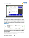
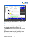
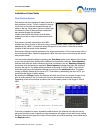
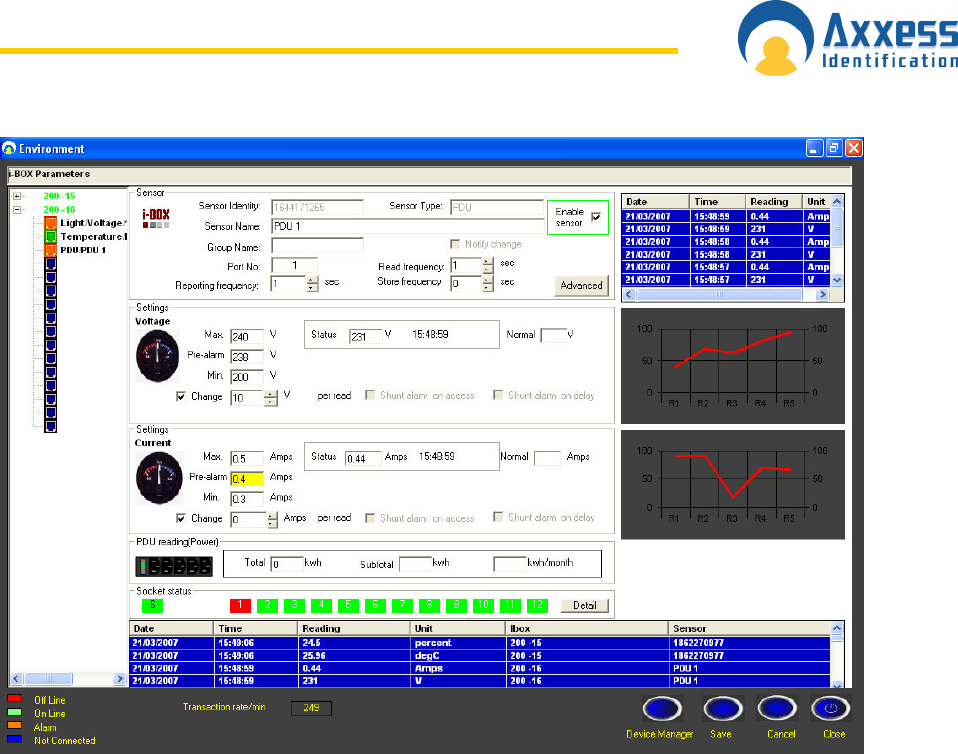
High and low limits could be defined for both voltage and current. Once the reading exceeds
these limits it will trigger an alarm and the appropriate transaction will appear on the main screen,
providing the sensor’s type, alarm description, i-BOX name and sensor ID.
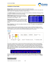
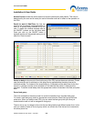
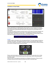
Details
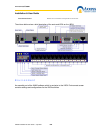
The status of the sockets is displayed on the left hand side. Each status has a unique colour.
Colour green means that the socket is switched on and colour red indicates that the socket is
switched off. If there is a fuse failure in any of the sockets, it will be displayed in amber and the
appropriate transaction will appear in the main screen. There is a space in front of every socket to
enter a brief description of the equipment connected to that particular socket.
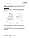
The Delay Start-up column includes the number of seconds before a socket is activated when
the PDU is switched on. If the input value is zero, the socket will not be switched on. (Range: 0s •
255s)
The Delay/Current column indicates the upper limit of the current in the unit before a particular
socket is switched on. For example if the input value for a particular socket is 5, it will not be
switched on until the current in the unit has dropped down to 5 amps or less.
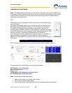
If there is a mismatch between the database and the PDU settings, these fields become yellow.
All you need to do is to press the save button to synchronize the database.