


www.axxessid.com
Installation & User Guide
AX200 Installation & User Guide – July 2007
14
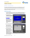
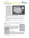
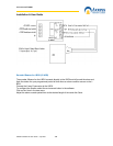
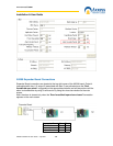
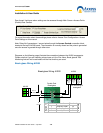
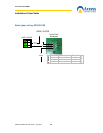
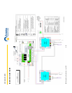
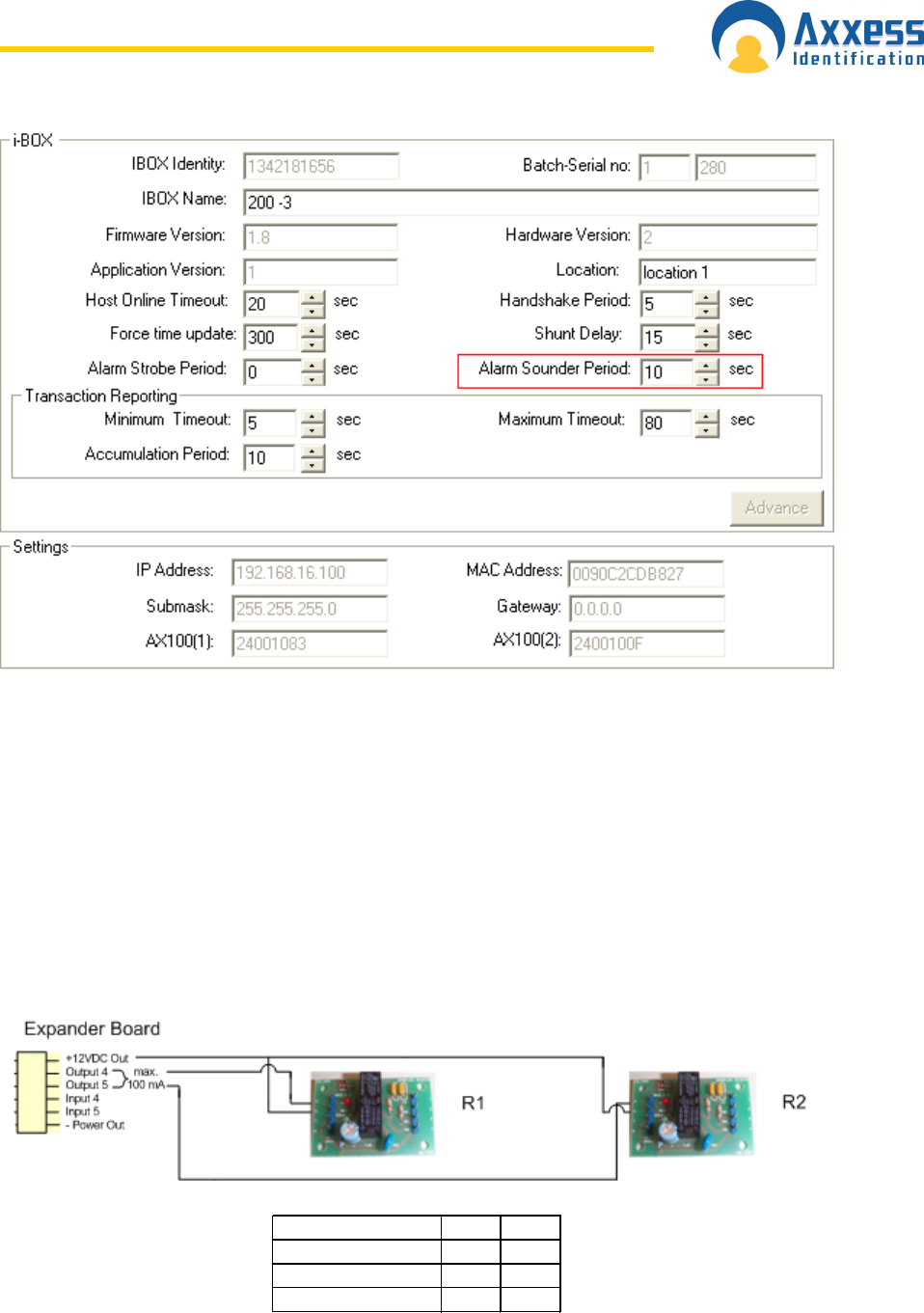
AX200 Expander Board Connections
Expander Board connections are located at the top-right corner of the AX200 board. Output 4
(associated with door 1) & output 5 (associated with door 2) are activated once the “Door
forced/held open alarm” is triggered on the appropriate controller and will stay active until the
alarm is cleared either by using a valid card or by using the clear alarm button on the main
screen.
Note: the alarm is cleared only when the “Door forced/held open alarm cleared” transaction
appears on the main screen.
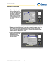
Expander Board R1 R2
12 VDC Out PIN 6 PIN 6
Output 4 PIN 5 -
Output 5 - PIN 5