


1-5
Installation and Configuration Guide for the CiscoWorks Wireless LAN Solution Engine
78-15903-01
Chapter 1 Product Overview
Hardware Features—CiscoWorks 1130 Wireless LAN Solution Engine
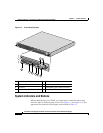
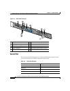
Back Panel Features
The back panel contains the AC power receptacle, keyboard connector, USB
connectors, Ethernet connectors, serial port, video connector, mouse connector,
system status indicator, and system identification button. Figure 1-3 shows the
back-panel features. The functions of the system status indicator and system
identification button are described in Table 1-1.
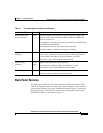
Table 1-1 Front-Panel System Indicators and Buttons
Indicator or Button Color Function
Power button and
power indicator
Green The power button controls power input to the power supply. The
indicator in the center of the power button indicates whether the
WLSE is powered on.
If the indicator is flashing, AC power is connected to the WLSE, but
the WLSE is not powered on.
If the indicator is not on, AC power is not connected.
The bezel contains a duplicate of the power indicator.
System identification
button(s)
Blue The system identification button on the front and back panels can be
used to locate a particular system in the rack. When you push the
system identification button, the blue indicators will flash.
This button is not visible with the bezel attached.
System status
indicator
Blue or
amber
Lights up during normal system operation.
If the indicator is amber flashing, the WLSE has a fault.
This indicator is not visible with the bezel attached.
Hard drive indicator Green Flashes when the hard drives are in use.
The bezel contains a duplicate of this indicator.