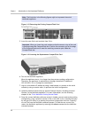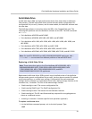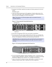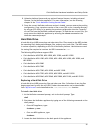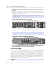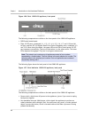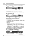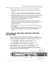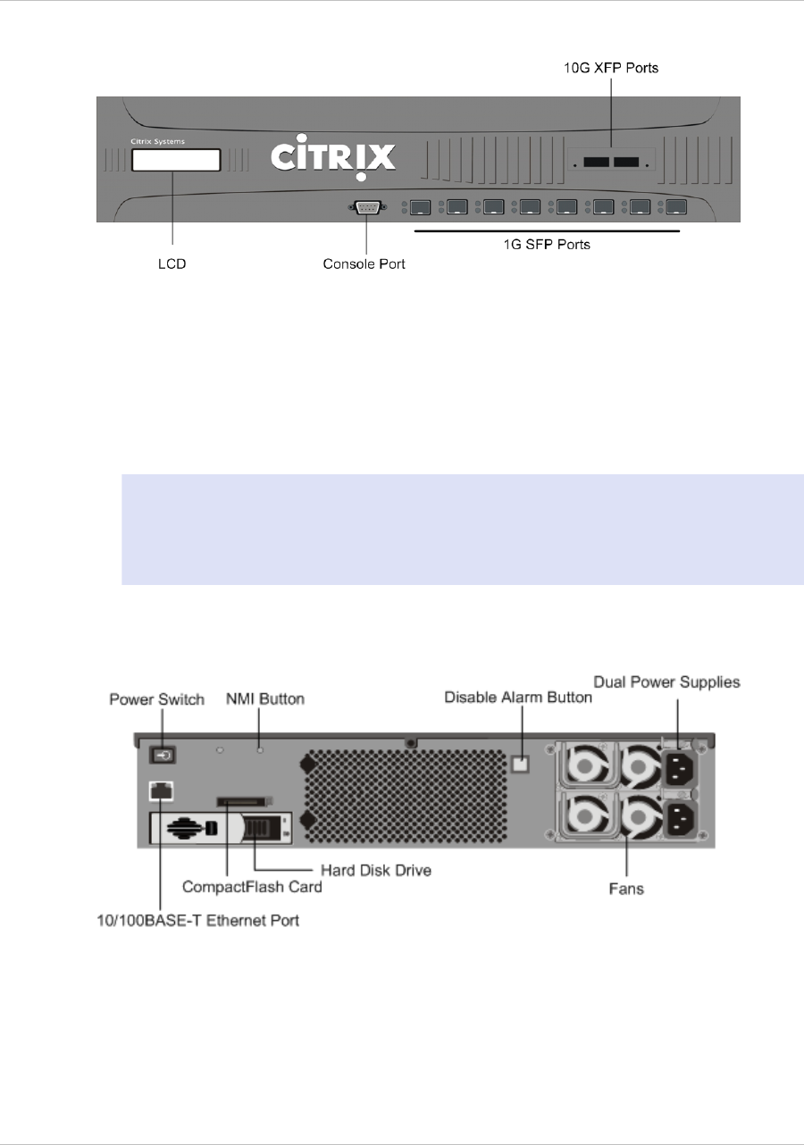
Figure 1-26. Citrix 12000-10G appliance, front panel
The following components are visible on the front panel of the 12000-10G appliance:
w
RS232 serial console port.
w
Eight 1G SFP ports, numbered 1/1, 1/2, 1/3, 1/4, 1/5, 1/6, 1/7, and 1/8 from left
to right, and two XFP (10-Gigabit Small Form-Factor Pluggable) ports, numbered 1/9
and 1/10. When facing the bezel, the upper LEDs to the left of each optical 1G SFP
port represent connectivity. They are lit and amber in color when active. The lower
LEDs represent throughput. They are lit and green when active.
Note: The network port numbers on all appliances consist of two numbers
separated by a forward slash. The first number is the port adapter slot number. The
second number is the interface port number. Ports on appliances are numbered
sequentially starting with 1.
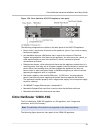
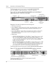
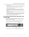
The following figure shows the back panel of the 12000-10G appliance.
Figure 1-27. Citrix NetScaler 12000-10G appliance, back panel
The following components are visible on the back panel of the 12000-10G appliance:
w
Power switch, which turns off power to the appliance, just as if you were to unplug
both power supplies.
w
Non-maskable interrupt (NMI) button, which signals the appliance to perform an
orderly shutdown after saving all files. You must use a pen, pencil, or other pointed
object to press this button, which is located inside a small hole to prevent it being
pressed accidentally.
Chapter 1 Introduction to the Hardware Platforms
40


