7-5
Fiber Matrix 6400 Switcher • Maintenance and Modications
100-240V 50/60Hz
1.2A MAX.
100-240V 50/60Hz
1.2A MAX.
REDUNDANT
PRIMARY
1 - 8
9 - 16
17 - 24
25 - 3233 - 40
41 - 48
49 - 5657 - 64
LAN
ACT
LINK
RESET
ANAHEIM, CA
PRIMARY POWER SUPPLY
REDUNDANT POWER SUPPLY
OUT
IN
A
OUT
IN
B
OUT
IN
C
OUT
IN
D
OUT
IN
E
OUT
IN
F
OUT
IN
G
OUT
IN
H
OUT
IN
A
OUT
IN
B
OUT
IN
C
OUT
IN
D
OUT
IN
E
OUT
IN
F
OUT
IN
G
OUT
IN
H
OUT
IN
A
OUT
IN
B
OUT
IN
C
OUT
IN
D
OUT
IN
E
OUT
IN
F
OUT
IN
G
OUT
IN
H
OUT
IN
A
OUT
IN
B
OUT
IN
C
OUT
IN
D
OUT
IN
E
OUT
IN
F
OUT
IN
G
OUT
IN
H
OUT
IN
A
OUT
IN
B
OUT
IN
C
OUT
IN
D
OUT
IN
E
OUT
IN
F
OUT
IN
G
OUT
IN
H
OUT
IN
A
OUT
IN
B
OUT
IN
C
OUT
IN
D
OUT
IN
E
OUT
IN
F
OUT
IN
G
OUT
IN
H
OUT
IN
A
OUT
IN
B
OUT
IN
C
OUT
IN
D
OUT
IN
E
OUT
IN
F
OUT
IN
G
OUT
IN
H
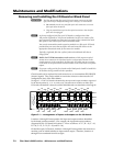
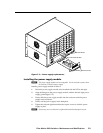
Align with Plastic Guides
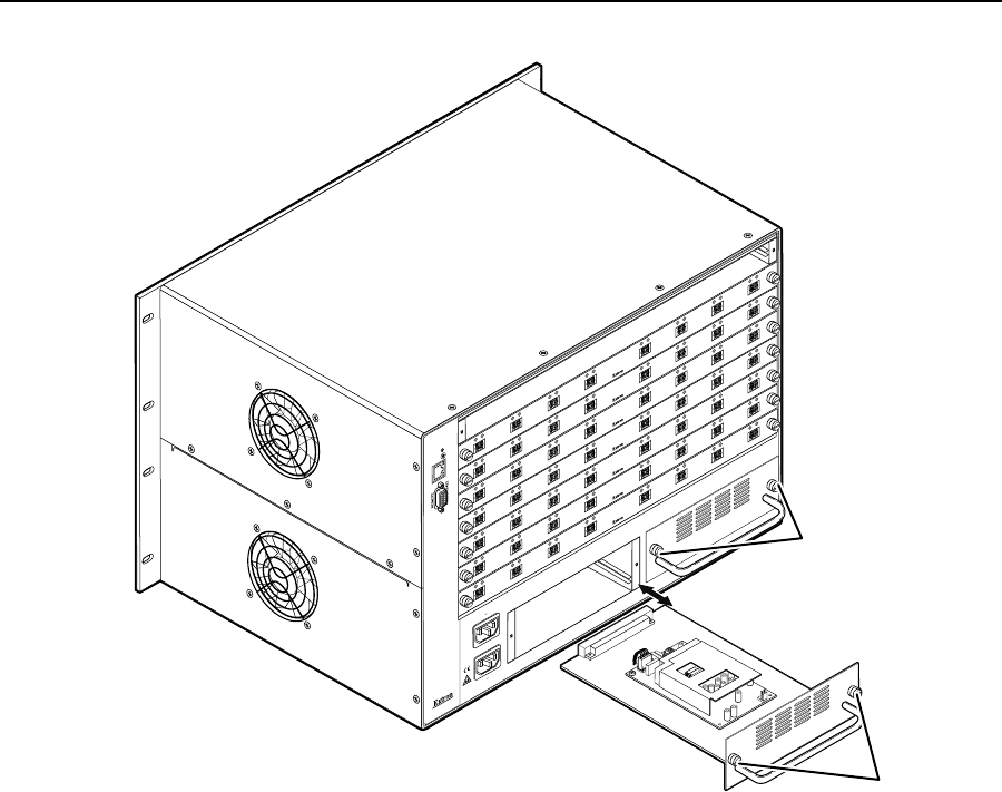
Knurled Knobs
Knurled Knobs
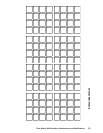
Figure 7-3 — Power supply replacement
Installing the power supply module
N
The power supply modules are hot-swappable. You do not need to power down
the switcher to install a power supply.
Install a power supply module as follows:
1. Orient the power supply module to be installed with the LED to the right.
2. Align the flanges on the power supply module with the left and right power
supply guides (figure 7-3).
3. Gently slide the power supply module into the enclosure until the power
supply meets resistance.
4. Gently seat the power supply in the backplane.
5. Tighten the left and right knurled knobs/captive screws to lock the power
supply in place.
N
If necessary, use a screwdriver to tighten the knurled knobs/captive screws.


