Programmer’s Guide, cont’d
Fiber Matrix 6400 Switcher • Programmer’s Guide
4-4
Ethernet (LAN) Port
The rear panel Ethernet connector on the switcher can be connected to an Ethernet
LAN or WAN. Communications between the switcher and the controlling device is
via telnet (a TCP socket using port 23). The TCP port can be changed if necessary,
via SIS. This connection makes SIS control of the switcher possible using a
computer connected to the same LAN or WAN. The SIS commands and the actions
of the switcher are identical to the commands and actions the switcher has when
communicating with it via RS-232.
Ethernet connection
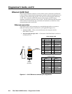
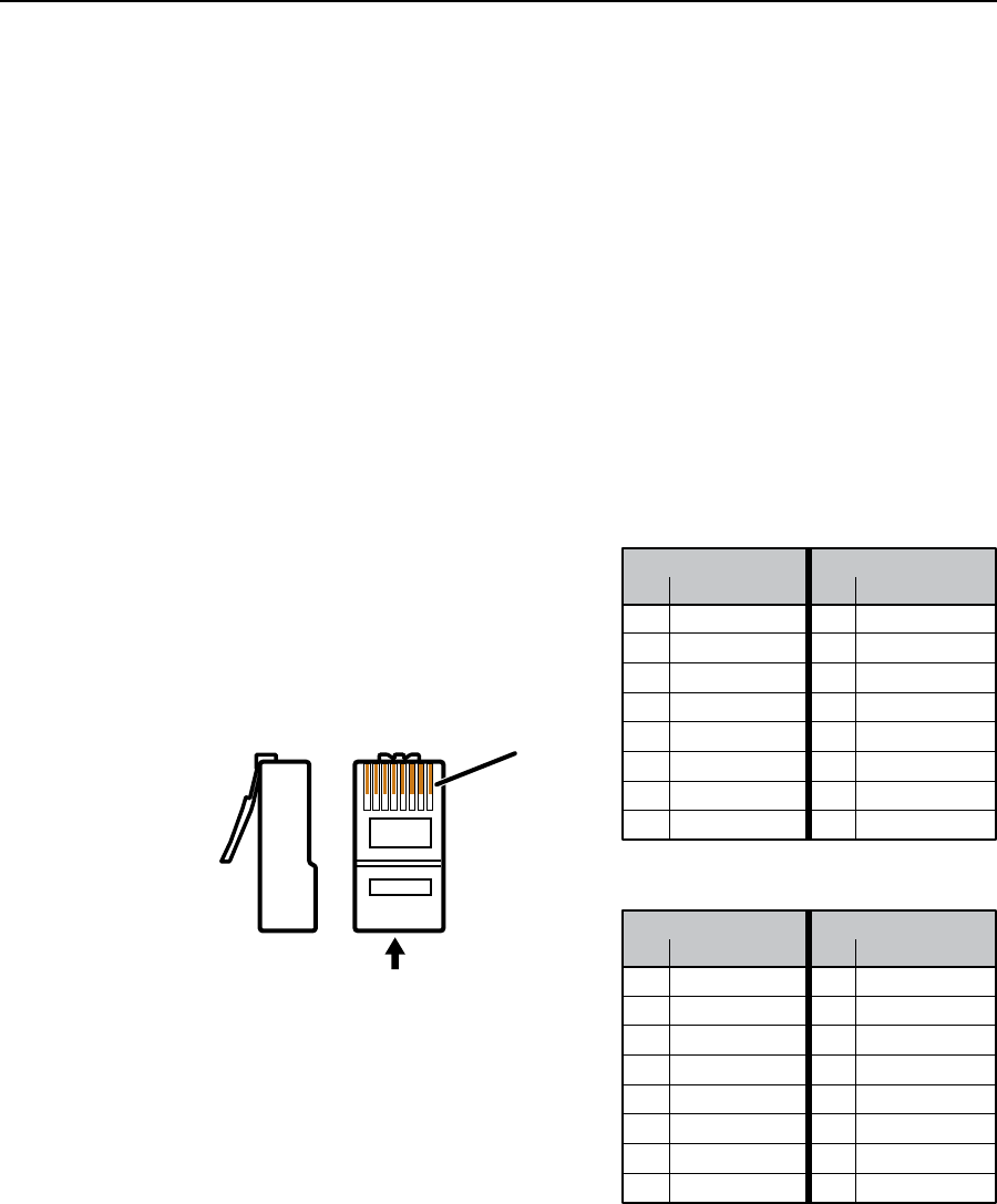
The Ethernet cable can be terminated as a straight-through cable or a crossover
cable and must be properly terminated for your application (figure 4-1).
• Crossover cable — Direct connection between the computer and the
Fiber Matrix switcher
• Patch (straight-through) cable — Connection of the Fiber Matrix switcher to
an Ethernet LAN
12345678
Insert
Twisted
Pair Wires
Pins:
RJ-45
connector
Patch (straight) cable
Side 1 Side 2
Pin Wire color Pin Wire color
1 White-orange 1 White-orange
2Orange 2Orange
3 White-green 3 White-green
4 Blue 4 Blue
5 White-blue 5 White-blue
6 Green 6 Green
7 White-brown 7 White-brown
8 Brown 8 Brown
Crossover cable
Side 1 Side 2
Pin Wire color Pin Wire color
1 White-orange 1 White-green
2Orange 2 Green
3 White-green 3 White-orange
4 Blue 4 Blue
5 White-blue 5 White-blue
6 Green 6Orange
7 White-brown 7 White-brown
8 Brown 8 Brown
Side
Figure 4-1 — RJ-45 Ethernet connector pin assignments


