Installation, cont’d
Fiber Matrix 6400 Switcher • Installation
2-8
Remote port
e
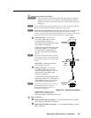
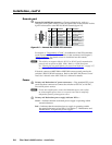
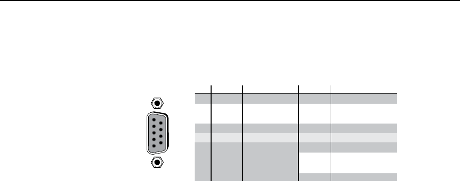
Remote RS-232/RS-422 connector — Connect a host device, such as a
computer, touch panel control, or RS-232 capable PDA to the switcher via this
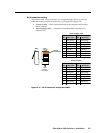
9-pin D connector for serial RS-232/RS-422 control (figure 2-5).
RS-232 Function Pin Function
1
2
3
4
5
6
7
8
9
—
TX
RX
—
Gnd
—
—
—
—
Not used
Transmit data
Receive data
Not used
Signal ground
Not used
Not used
Not used
Not used
—
TX–
RX–
—
Gnd
—
RX+
TX+
—
Not used
Transmit data (–)
Receive data (–)
Not used
Signal ground
Not used
Receive data (+)
Transmit data (+)
Not used
RS-422
5
1
9
6
RS232/RS422
REMOTE
Figure 2-5 — Remote RS-232/RS-422 connector
See chapter 4, “Programmer’s Guide”, for definitions of the SIS commands
(serial commands to control the switcher via this connector) and chapter 5,
“Matrix Software”, for details on how to install and use the control/
configuration software.
N
The switcher can support either the RS-232 or RS-422 serial communication
protocol, and can operate at 9600, 19200, 38400, or 115200 baud rates.
See “Selecting the rear panel Remote port protocol and baud rate” on page 3-27,
to configure the RS-232/RS-422 port from the front panel.
If desired, connect an MKP 2000 or MKP 3000 remote control panel to the
switcher’s RS-232/RS-422 connector. Refer to the MKP 2000 Remote Control
Panel User’s Manual or the MKP 3000 User’s Manual for details.
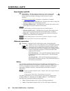
Power
f
Primary and Redundant AC power connectors — Plug standard IEC power
cords into these connector to connect the switcher to 100 VAC to 240 VAC,
50 or 60 Hz power sources.
N
For the most reliable power, connect the Redundant power cord to either
an uninterruptible power source or to a power source that is completely
independent from the primary power source.
g
Primary and Redundant power supply indicator LEDs —
Green — Indicates that the associated power supply is operating within
normal tolerances.
Red — Indicates that the associated power supply is operating outside
the normal tolerances or has failed. See chapter 7, “Maintenance and
Modifications“ to replace the power supply.


