Installation, cont’d
Fiber Matrix 6400 Switcher • Installation
2-4
I/O boards
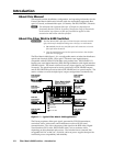
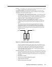
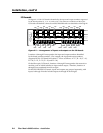
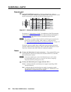
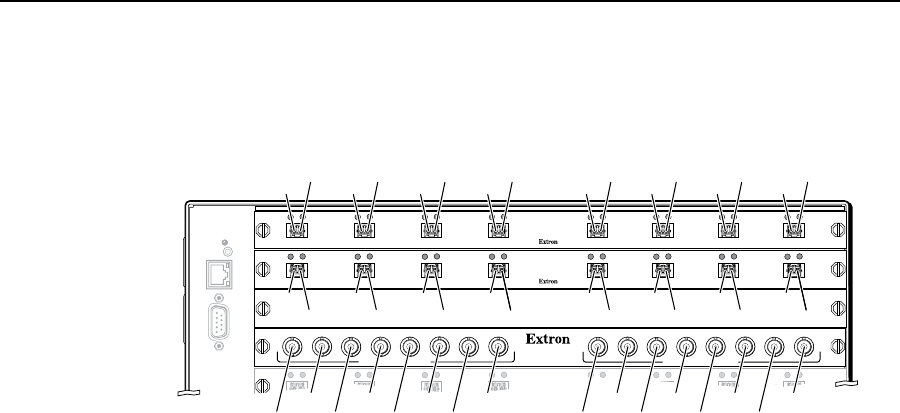
See figure 2-2. Each I/O board is identified by the input and output numbers supported
by the board position (1 - 8, 9 - 16, and so on). The transceiver modules on fiber optic
I/O boards and the BNC connectors on SDI/HD-SDI boards are identified as A through H.
RESET
RS232/RS422
REMOTE
LAN
ACT
LINK
1 - 8
9 - 16
17 - 24
25 - 3233 - 40
OUT
IN
A
OUT
IN
B
OUT
IN
C
OUT
IN
D
OUT
IN
E
OUT
IN
F
OUT
IN
G
OUT
IN
H
OUT
IN
A
OUT
IN
B
OUT
IN
C
OUT
IN
D
OUT
IN
E
OUT
IN
F
OUT
IN
G
OUT
IN
H
OUT
IN
OUT
IN
OUT
IN
OUT
IN
OUT
IN
OUT
IN
OUT
IN
OUT
IN
MUTI-RATE SDI INPUTS
H
G
AD
E
F
C
B
MUTI-RATE SDI OUTPUTS
H
G
AD
E
F
C
B
Slot 1
O#1
I#1
Slot 2
Slot 3
No board
installed
Slot 4
O#2
I#2
O#3
I#3
O#4
I#4
O#9
I#25
I#26
I#27
I#28
I#29
I#30
I#31
I#32
O#25
O#26
O#27
O#28
O#29
O#30
O#31
O#32
I#9
O#10
I#10
O#11
I#11
O#12
I#12
O#5
I#5
O#6
I#6
O#7
I#7
O#8
I#8
O#13
I#13
O#14
I#14
O#15
I#15
O#16
I#16
Figure 2-2 — Arrangement of inputs and outputs on the I/O boards
Locations A through H correspond to the input and output numbers identified
by the board position numbers. (For example, the input and output numbers
supported by the I/O board in location 17 - 24 are as follows: A = 17, B = 18, C = 19,
D = 20, E = 21, F = 22, G = 23, and H = 24.)
On the fiber optic I/O boards, locations A through H correspond to the transceiver
modules, each of which includes an input and an output. Therefore, locations A
through H are numbered from left to right.
On the SDI/HD-SDI I/O boards, inputs and outputs are grouped separately, with
inputs A through H on the left and outputs A through H on the right.


