


Programmer’s Guide, cont’d
Fiber Matrix 6400 Switcher • Programmer’s Guide
4-8
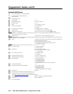
Symbol definitions
]
= CR/LF (carriage return/line feed) (hex 0D 0A)
}
= Carriage return (no line feed, hex 0D)
• = Space character
E
= Escape key (hex 1B))
X!
= Input number 01 – 64
X@
= Input number (for tie)
00
–
64 (00 = untied)
X#
= Output number 01 – 64
X$
= Mute 0 = not muted, 1 = muted
X%
= Output re-clocking rate 00 = auto (default)
01 = bypass
X^
= Group # (for I/O grouping) 1 through 4 groups (0 = no group)
X&
= Global preset # 00 – 64 maximum (0 = current configuration)
X*
= Room # (for room presets) 10 max. (each can have up to 10 presets (
X(
) assigned)
N
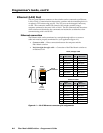
A Room is a subset of operator-selected outputs that relate to each other. The Fiber Matrix switcher supports up to 10 rooms, each of
which can consist of from 1 to 16 outputs.
X(
= Room preset # 10 maximum (0 = current configuration for room)
N
A Room preset is a stored configuration with all of the outputs assigned to a single room.Whenaroom preset is retrieved from memory,
it becomes the current configuration.
X1)
= Name 12 characters maximum for input names, output names, global preset
names, and room preset names
11 characters maximum for room names
Upper- and lower-case alphanumeric characters and
_ / and spaces are valid.
N
The following characters are invalid in the name: {space} ~ , @ = ‘ [ ] { } < > ’ “ ; : | \ and ?.
X1!
= Connection status 0 = no input connected
1 = input connected
X1@
= Output rate: nnnn = actual rate (in MHz)
0000 = no connection or rate mismatch
- - - - = bypass mode
X1#
= Lock mode, power supply 0 = unlocked/not OK
1 = locked/OK
X1$
= Number (quantity) of inputs 8, 16, 24, 32, 40, 48, 56, or 64
X1%
= Number (quantity) of outputs 8, 16, 24, 32, 40, 48, 56, or 64
X1^
= Board installed 0 = No board installed
1 = 8x8 multimode board
2 = 8x8 singlemode board
3 = SDI/HD-SDI board
x = Unknown board or mix of transceivers installed
X1&
= I/O board slot number 1 – 8
X1*
= Fiber optic transceiver module installed 0 = No module installed
1 = Multimode module
2 = Singlemode module
3 = SDI-HD-SDI board (all I/Os on board)
X1(
= Part number 68-878-01
X2)
= Firmware version number to second decimal place (x.xx)
X2!
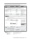
= Verbose firmware version-description-upload date/time.
See the Query firmware version (verbose) command on page 4-16.
X2@
= Voltage Positive or negative voltage and magnitude
X2#
= Temperature Degrees Fahrenheit
X2$
= Fan speed (in RPM)