


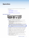
Cabling
This section describes how to connect cables to a DVS 304 series device.
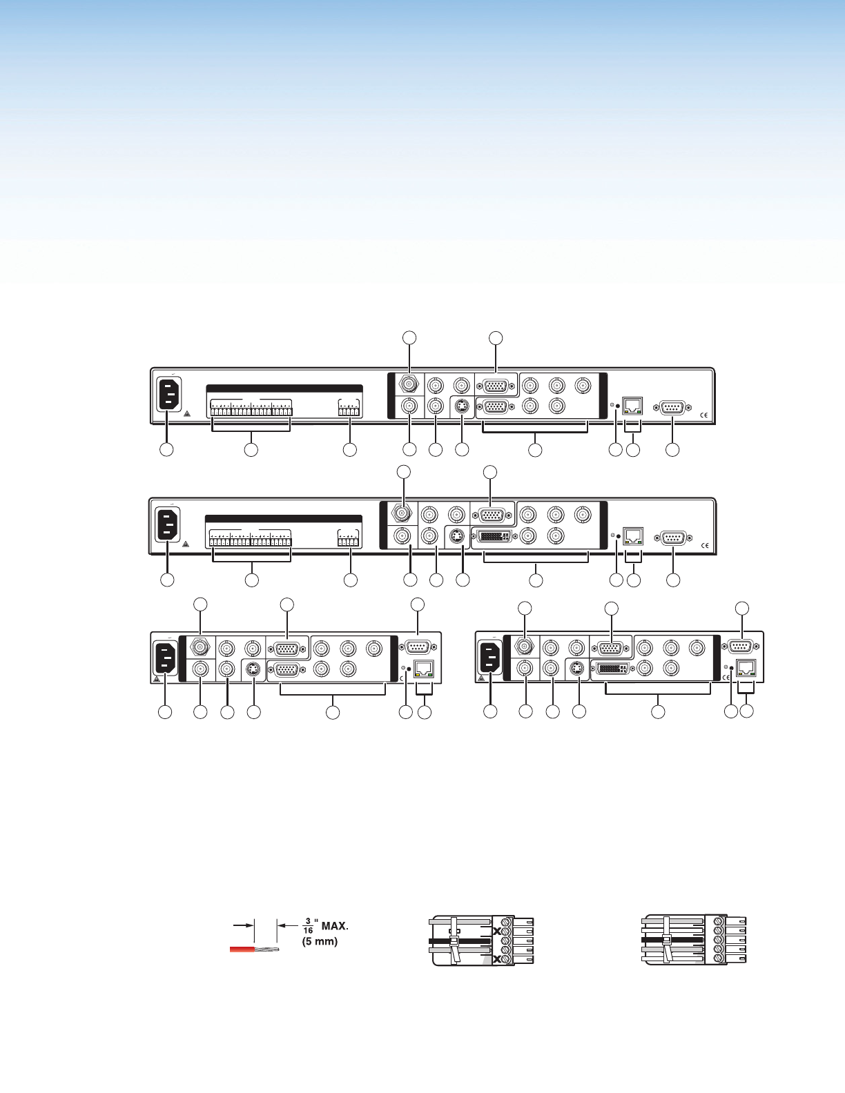
Rear Panel Cabling
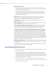
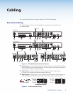
The illustration below shows the all possible rear panel features of the audio and
non-audio models.
INPUTS OUTPUT
VID
1
2
3
4
Y
/VID
R-Y
H/
HV
R
/R-Y
V
G
/Y
B
/B-Y
RS-232
LAN
RESET
ACTLINK
RGB/R-Y,Y,B-Y
YC
SDI
B-Y
/C
RGB/R-Y,Y,B-Y/YC/VID
I
N
P
U
T
O
U
T
P
U
T
50/60 Hz
100-240V .3A
2
1
3
4
LR
LR
LR
LR
LR
I
N
P
U
T
O
U
T
P
U
T
AUDIO
8
5
4
3
6
7
10
1
2
12
9
11
VID
50/60 Hz
1
2
3
4
Y
/VID
R-Y
H/
HV
R
/R-Y
V
G
/Y
B
/B-Y
RS-232
LAN
RESET
ACTLINK
RGB/R-Y,Y,B-Y
YC
SDI
B-Y
/C
RGB/R-Y,Y,B-Y/YC/VID
100-240V .3A
I
N
P
U
T
O
U
T
P
U
T
4
5
6
7
10
1
9
12
11
8
INPUTS OUTPUT
RS-232
LAN
RESET
ACTLINK
50/60 Hz
100-240V .3A
2
1
3
4
LR
LR
LR
LR
LR
AUDIO
VID
1
2
3
4
Y
/VID
R-Y
H/
HV
R
/R-Y
V
G
/Y
B
/B-Y
DVI-I
YC
SDI
B-Y
/C
RGB/R-Y,Y,B-Y/YC/VID
I
N
P
U
T
O
U
T
P
U
T
8
5
4
3
6
7
10
1
2
12
9
11
4
Y
/VID
R
/R-Y
G
/Y
B
/B-Y
RS-232
LAN
RESET
SDI
B-Y
/C
RGB/R-Y,Y,B-Y/YC/VID
100-240V .3A
I
N
P
U
T
O
U
T
P
U
T
VID
50/60 Hz
1
2
3
R-Y
H/
HV
V
ACTLINK
DVI-I
YC
4
6
7
10
1
9
11
5
12
8
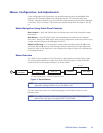
DVS 304 D
DVS 304 DVI D
DVS 304 DVI AD
DVS 304 AD
(Optional)
(Optional)
(Optional)
(Optional)
Figure 1. DVS 304 Devices Rear Panel Features
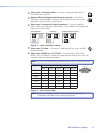
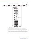
a
Power input — Connect the standard IEC power cord from a 100 to 240 VAC, 50 Hz
or 60 Hz power source into this connector. The front panel control and input selection
buttons light in sequence during power-up.
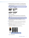
b
Audio input — Plug in up to four, 3.5 mm, female, ve-pole, captive screw
connectors for balanced/unbalanced variable audio input.
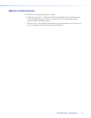
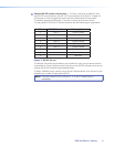
c
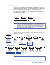
Audio output — Plug in one, 3.5 mm, female, ve-pole captive screw connector for
balanced/unbalanced variable audio output. Wire the connector as shown below.
L
MONO AUDIO
R
L
MONO AUDIO
R
Unbalanced Output
Balanced Output
Do not tin the wires!
Mono output 1-
Sleeve(s)
Mono output 1+
Mono output 2+
Mono output 2-
Sleeve(s)
Mono output 1
Mono output 2
NO GROUND.
NO GROUND.
Figure 2. Audio connector wiring
DVS 304 Series • Cabling 5