


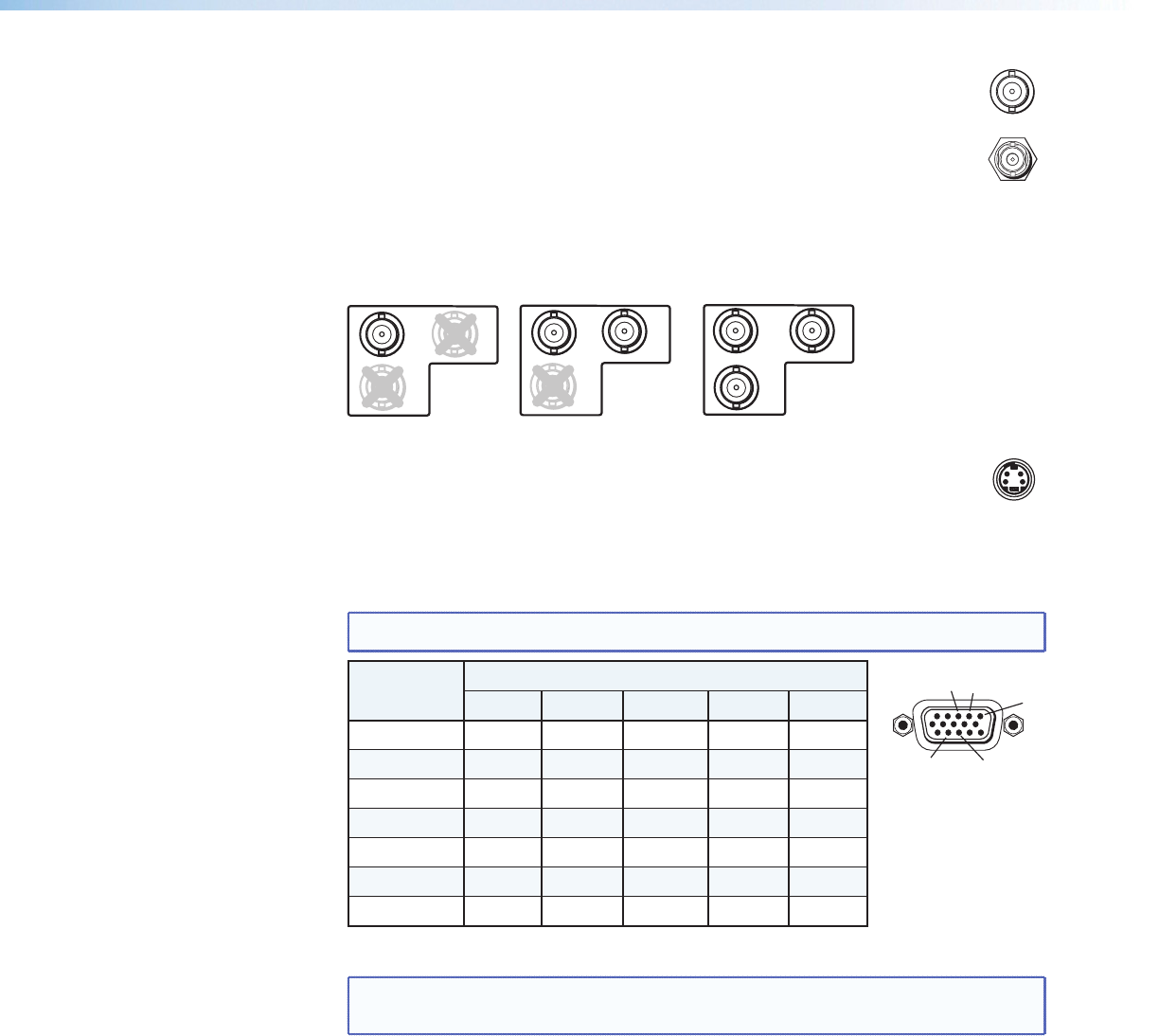
d
Video input 1: Composite video — Connect a composite video signal to
this female, BNC connector.
e
Optional SDI (serial digital interface) input connector — Connect an
SDI signal to this female BNC connector. During setup, the SDI input can be
assigned to one of the other unused inputs.
f
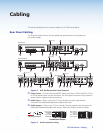
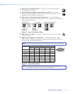
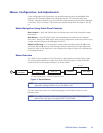
Video input 2: Composite/S-video/Component — Connect composite
video, S-video, and component video signals. Connect cables for the appropriate
signal type, as shown here.
Composite Video
2
Y
/VID
B-Y
/C
R-Y
2
R-Y
Y
/VID
B-Y
/C
C
omponent Video (Y, R-Y, B-Y)
2
B-Y
/C
S-video (YC)
Y
/VID
R-Y
Figure 3. Input 2 Connector Cabling
g
Video input 3: S-video — Connect an S-video signal to this 4-pin, mini-DIN
female connector.
h
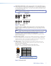
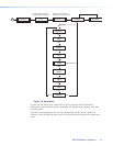
Video input 4: RGB/R-Y, Y, B-Y/YC/VID — Connect RGBHV, RGBS, RGsB,
RGBcvS, YUVi, YUVp/HDTV, S-video and composite video through this 15-pin HD
connector. See pin configurations below.
NOTE: DVS 304 DVI models feature EDID emulation on this 15-pin HD connector.
Signal Input 4 Conguration
Pin 1 Pin 2 Pin 3 Pin 13 Pin 14
RGBHV R G B H V
RGBS R G B S
RGBcvS R G B S
RGsB R Gs B
YUV R-Y Y B-Y
S-video Y C
Video Vid
Figure 4. Input 4 Pinout Table
NOTE: Equipment following the SCART interconnection standard may be
connected to the RGBcvS input cabling conguration.
SDI
1
VID
3
YC
1
2
13
3
14
DVS 304 Series • Cabling 6