


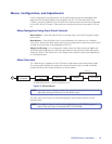
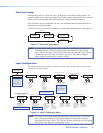
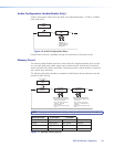
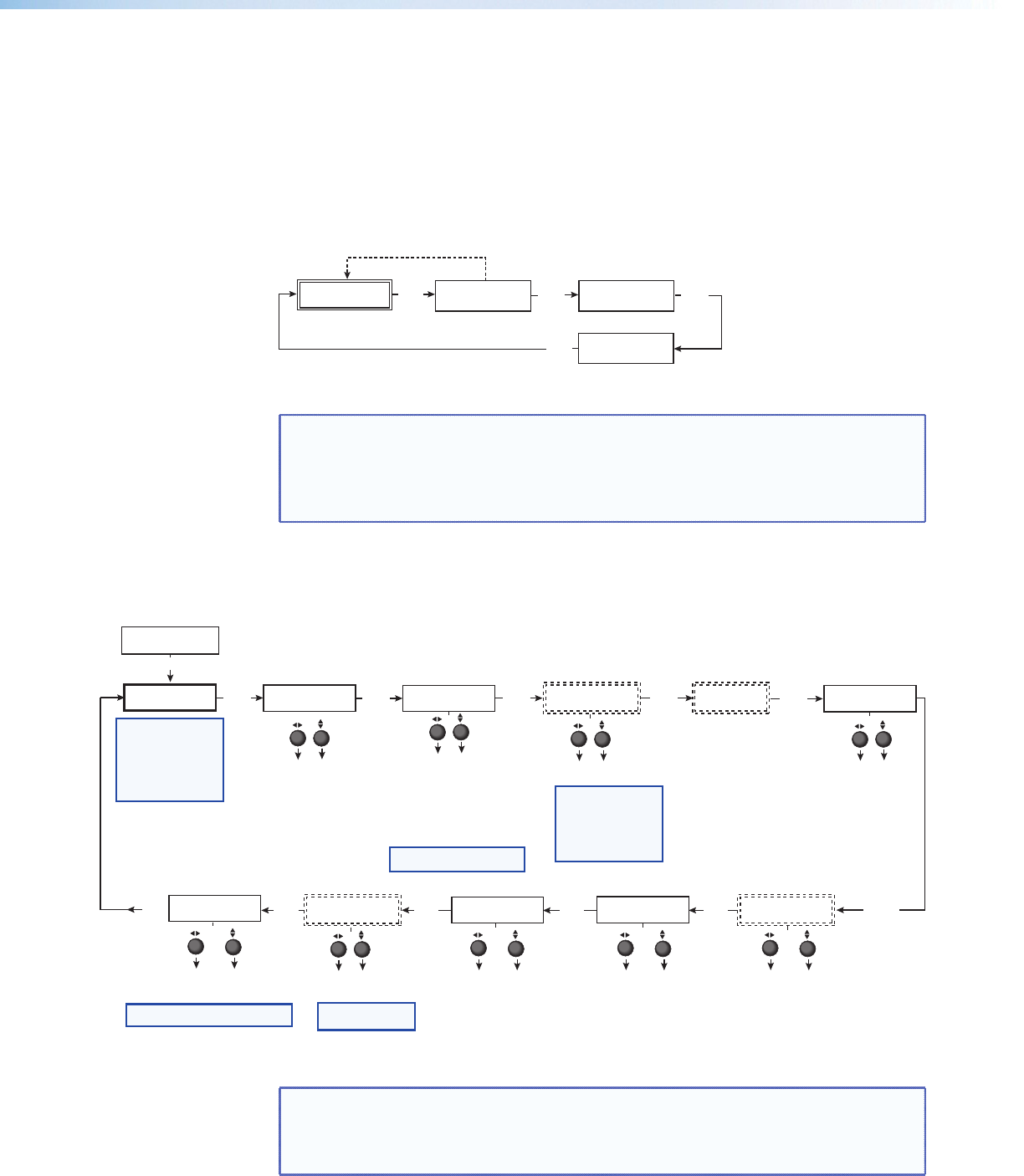
Start Auto Image
Auto image an input to “auto size” and “auto center” the image to ll the screen. The
processor measures the sync frequencies from incoming video sources and uses an internal
table to set the active image area, total image area, and the sampling frequency.
If an unknown input is connected to the unit, the processor measures and estimates the
resolution of the incoming video.
The DVS 304 can be set to automatically auto-image newly detected inputs (see page 21).
Default Cycle
INPUT 1
COMPOSITE
2 sec.
2 sec.
OUTPUT
1024 x 768@60
MENU
START AUTO
IMAGE ON IN1
PRESS NEXT
TO START
NEXT
NEXT
Figure 11. Start Auto Image Menu
NOTE: An input with a vertical refresh rate less than 40 Hz will have to be manually
centered and sized, using H/V Start and H/V Active under the Input Cong
menu. When a rate with a low vertical refresh rate (for example 720p, 29.9 Hz)
is applied and an auto image command is issued, the DVS refers to default
values instead of performing a true auto image.
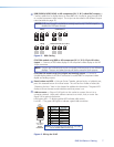
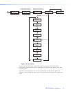
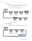
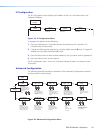
Input Conguration
The following flowchart provides an overview of the Input Configuration submenus and
the options for each setting.
START AUTO
IMAGE ON IN1
INPUT
CONFIG
MENU
NEXT
INPUT 2
YUVi
INPUT 4
RGB SCALED
NEXT
ASPECT RATIO
4x3
TTLPIX PHASE
XXXX 08
NEXT
NEXT
NEXT
H START V
50 33
H ACTIVE V
XXX XXX
NEXT
FILM MODE
<OFF> ON
SDI INPUT
<
*
> 1 2 3 4
NEXT
NEXT
Displays only when applicable
Displays only when applicable Displays only when applicable
SDI DE-INTER
FIELD STNDRD
NEXT
Displays only when applicable
NEXT
DVS 304 DVI models only
Displays only on Input 4
NEXT
Select video format
• Composite
• S-video
• YUVi
• YUVp/HDTV
• YUV Auto
Assign SDI to Input #
• 1, 2, 3, 4, * (none)
Select video format
• Composite
• S-video
• RGBcvS
• YUVi
• YUVp/HDTV
• RGB scaled
• RGB pass*
• Auto detect
Aspect ratio options
• 4 x 3
• 16 x 9
For YUVp or RGB input only
Total pixels
Specify the width
in pixels of the
total image area
sampled.
Pixel phase
Adjust the pixel
sampling point for
a selected input.
Horizontal start
Select for the
left edge of the
active video.
Vertical start
Select for the
top edge of the
active video.
Horizontal active
pixels
Specify the width
in pixels of the
active image area
sampled.
Vertical active
lines
Specify the
height in lines of
the active image
area sampled.
Film mode
Turn On or Off for low
resolution devices.
SDI De-interlacing options:
• Field Standard
• Field Flip
VGA EDID
1024x768@60
EDID Emulation
Specify the resolution
and refresh rate.
NOTE:
Input 1 can only
accept composite video.
Input 3 can only accept
S-video. Only Inputs 2 and
4 can be configured for
different video types,
although an SDI input can
be assigned to any input.
NOTE: The SDI input signal
can be assigned to any
input. Once assigned to a
specific input, only an SDI
signal can be accepted on
that input. SDI can be
disabled by selecting the *.
NOTE: See table in the “Resolutions
and Refresh Rates” section, for EDID values.
NOTE: Not for use with
YUVp or RGB inputs.
NOTE:
* RGB pass through is only
available on analog outputs.
Figure 13. Input Configuration Menu
NOTE: Only inputs 2 and 4 offer selectable video types. From the Input Conguration
menu, pressing the Next key successively displays submenus with the input
video types for Inputs 2 and 4. The SDI input (where applicable) can be assigned
to any input from the Input Configuration menu.
DVS 304 Series • Operation 12