


Menus, Conguration, and Adjustments
Scaler conguration and adjustments can be performed by using the embedded Web
pages and the Windows-based control program (see the “SIS Communication and
Control” chapter for details) or by using the front panel controls and the menus displayed
on the DVS unit’s LCD screen. These menus are used primarily when the scaler is rst set
up.
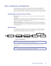
Menu Navigation Using Front Panel Controls
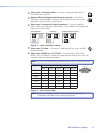
Menu button — Press the Menu button to activate menus and scroll through the eight
main menus.
Next button — Press the Next button to move between the submenus of a selected
main menu. Pressing the Next button during input configuration causes the current input’s
number and format type to be displayed on the LCD.
Adjust ([,{) knobs — In configuration mode, rotate the Adjust horizontal ([) knob
and Adjust vertical ({) knob to scroll through submenu options and to make adjustment
selections. Refer to the flowcharts in this chapter and to specific sections for explanations
on knob adjustments.
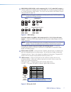
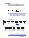
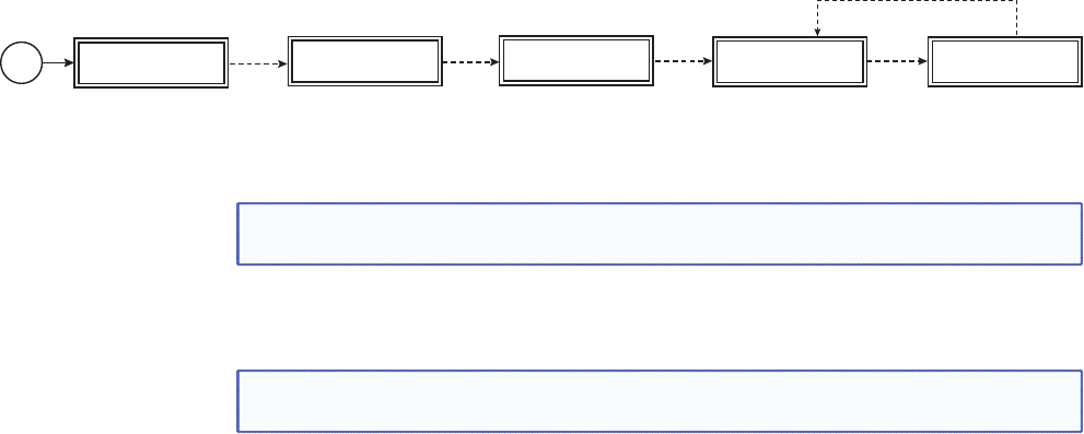
Menu Overview
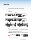
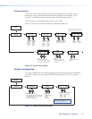
The “default cycle” appears on the LCD when no adjustments are actively being made.
The screens cycle between the screen that shows the active input’s number and video
format and the current output resolution, as shown below
DVS 304
xxx xx
2 sec.
INPUT 1
COMPOSITE
60-xxxx-xx
FW ver. 1.xx
2 sec.
2 sec.
OUTPUT
1024 x 768@60
Default Cycle
2 sec.
Power
on
EXTRON
ELECTRONICS
2 sec.
Displays specific model name
(for example DVS 304 DVI AD)
Displays specific model part
number (for example 60-1027-04)
Figure 9. Default Menus
NOTE: From any menu or submenu, after 20 seconds of inactivity the DVS will save all
adjustment settings and time-out to the default cycle.
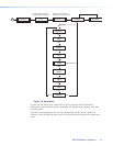
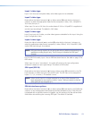
The main menus are shown on the following pages. Use the Menu button to scroll
between them.
NOTE: If no signal is present on the currently selected input, NO SIGNAL appears in
place of the input type, for example, INPUT 4 NO SIGNAL.
DVS 304 Series • Operation 10