


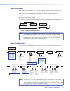
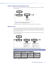
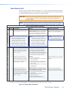

OSD label
Use the On-Screen Display (OSD) label menu to determine the time allotment for an input
label or a user defined OSD label. Input labels are generic labels shown for inputs 1, 2
and 3. For input 4, the user can create a custom OSD label to display.
The OSD labels are displayed (white box, black text) in the top left corner.
The OSD label can be turned off by setting its duration to Off from the Advanced
Configuration menu.
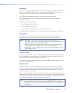
For OSD text, note the following:
• Line 1 displays the input number.
• Line 2 displays the input type.
• Line 3 displays a text label that you can dene (input 4 only).
The display time can be set from 0 to 5 seconds in 1 second steps (default is 2 seconds).
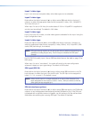
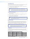
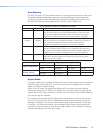
Test pattern
Test patterns are useful for calibrating a display to the DVS 304 output. Choose a test
pattern to adjust the image using built in crop, alternating pixels, and color bars.
NOTE: • Alt Pixels — Used to calibrate display devices input sampling to the
DVS 304’s output. Use this pattern to adjust the clocking and phasing at the
display until no more vertical bands are visible.
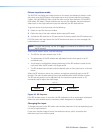
• Crop — Used to center the DVS 304’s output on the display device: adjust
H and V center on the display until all four crop lines are visible.
• Color Bars — Used to calibrate color settings on the display and to conrm
proper system wiring.
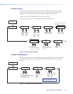
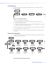
Enhance mode
When the enhance mode is set to on, automatic gain control of the low resolution input
signal is enabled. If the input signal level is too weak, signal gain is increased, and if the
input signal level is excessive, signal gain is decreased.
Using either the Adjust horizontal ([) or Adjust vertical ({) knob, select either On or Off
as desired. The default is Off.
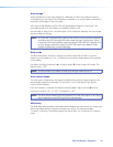
Refresh Lock
When Refresh Lock is enabled, the vertical output rate is locked to the current input’s
vertical refresh rate to prevent tearing and/or stuttering associated with frame conversion.
This mode should be activated only when excessive stuttering and/or tearing is being
experienced with an input signal.
Because the output’s vertical sync is linked to the current input’s vertical sync while in the
Refresh Lock mode, there may be a slight glitch in the output sync whenever a new source
is applied to the scaler, or whenever a new input is selected. This is caused by the scaler
instantly locking its refresh rate to that of the new input signal.
NOTE: The output refresh rate must be set equal to or greater than the incoming
video’s refresh rate or no video output will be displayed. If the incoming video’s
vertical rate differs significantly from the set output refresh rate, no video will
be displayed.
DVS 304 Series • Operation 20