


Operation
This section of the manual discusses the operation of a DVS 304 device, and is divided
into four sections:
• Front Panel Overview
• Menus, Configuration, and Adjustments
• Front Panel Lockout
• Setting up the DVS to Work with a Matrix Switcher
Front Panel Overview
1
DVS 304
VIDEO AND RGB SCALER
ADJUST
IR
2 3 4 MENU NEXT
3
4
5
6 7
2
1
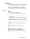
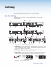
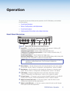
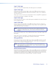
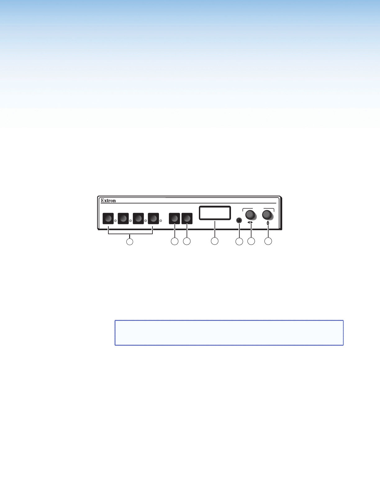
Figure 8. Typical DVS 304 Device Front Panel Features
a
Input LEDs — The LED of the selected input lights when pressed. A blinking LED
indicates an audio breakaway input (audio models only).
Composite input button — Input 1 selects composite video input.
Composite/YC/component input button — Input 2 selects composite video, YC,
or component video input.
S-video input button — Input 3 selects the S-video input.
Universal input button — Input 4 selects the RGB scaled (RGBHV, RGBS, RGsB), RGB
pass-through, YUVi, YUVp/HDTV, S-video and composite video.
NOTE: RGB pass-through signals (at native rate without additional processing) are
available on analog outputs only. The DVI output is disabled for
pass-through.
b
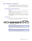
Menu button — Use this button to enter and move through the main menu system
for the scaler. See the “Menus, Conguration, and Adjustments” section for details.
c
Next button — Use this button to step through the submenus in the scaler menu
system. See the “Menus, Conguration, and Adjustments” section in for details.
d
LCD display — Displays configuration menus and status information. See the
“Menus, Conguration, and Adjustments” section in this chapter for details.
e
Infrared sensor — This sensor is used to receive infrared (IR) signals from the IR 902
remote control. See the “IR 902 Infrared Remote Control” section for details.
f
Adjust horizontal ([) knob — In the menu system, rotate this knob to scroll
through menu options and make adjustments.
g
Adjust vertical ({) knob — In the menu system, rotate this knob to scroll through
menu options and make adjustments.
DVS 304 Series • Operation 9