


Programmer’s Guide, cont’d
CrossPoint 450 Plus and MAV Plus Switchers • Programmer’s Guide
4-14
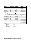
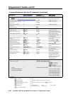
Command/response table for SIS commands (continued)
Command ASCII command
(host to switcher)
Response
(switcher to host)
Additional
description
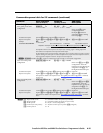
View ties, gain, volume, mutes, and presets
N
The & view tie command for RGB and % view tie command for video can be used interchangeably.
View video and audio
output tie
X@
!
X!]
Input
X!
video and audio is
tied to output
X@
.
Example:
15! 27] Input 27 video and audio
tied to output 15.
View RGB output tie
X@
&
X!]
Input
X!
RGB is tied to
output
X@
.
Example:
7&
02
]
Input 2 RGB is tied to output 7.
View video output tie
X@
%
X!]
Input
X!
video is tied to
output
X@
.
Example:
3%
06
]
Input 6 video is tied to
output 3.
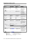
View output volume
X@
V
X*]
View input gain
X$
G
X^]
View output mutes
E
VM
} X1#
1
,
X1#
2
, ...
X1#
n
]
Each
X1#
response is the mute
status of an output, starting
from output 1. n is the
highest-numbered output.
Example:
E
VM
}
Mut00001000000230000000000000000000
]
CrossPoint 450 Plus 6432 HVA
Output 5 video is muted,
output 12 audio is muted,
and output 13 video and
audio are muted. All other
outputs are unmuted.
N
The “Mut” portion of the response appears only when the switcher is in Verbose mode 2 or 3. See the "Set verbose
mode" command on page 4-23.
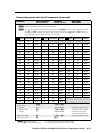
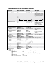
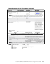
View global preset video
configuration
EX(
*
X@
*1VC
}
X!
n
•
X!
n
+1
•...•
X!
n
+15
•Vid
]
Show preset
X(
’s video
configuration. Show
the input (
X@
) tied to 16
sequential outputs, starting
from output
X@
.
Command description:
Response description:
preset # (
X(
)*starting output # (
X@
)*1(=video)VC
input # (
X!
) tied to
X@
•
X!
tied to
X@
+1•
X!
tied to
X@
+2• ... •
X!
tied to
X@
+15•Vid
]
Example:
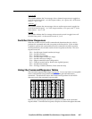
MAV Plus 6432
E
23*1*1VC
}
17Output:
Response = tied input:
input 34 tied to output 19
18 19 20 21 22 23 24 25 26 27 28
08•08•34•08•08•49•49•00•08•01•01•01•08•08•08•08•Vid
29 30 31 32
no tied input input 8 tied to output 29
Each position shown in the response is an output: left = starting, right = starting output+15.
The number in each position is the input tied to that output.
In this example, input 1 is tied to outputs 26 through 28; input 8 to outputs 17, 18, 20, 21, 25,
and 29 through 32; input 34 to output 19; and input 49 to outputs 22 and 23.
No input is tied to output 24.
N
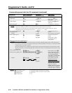
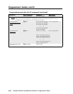
EX(
*
X@
*1VC
}
where
X(
= 0 returns 16 tied outputs of the switcher’s current video configuration.
N
X!
= Input number for tie
01
–
(maximum number of inputs for your model)
X@
= Output number 01 – (maximum number of outputs for your model)
X^
= Numeric dB value –18 to +24 (45 steps of gain or attenuation)
X*
= Volume adjustment range 0 – 64 (1 dB/step except for 0-to-1, which is 12.5 dB)
X(
= Global preset # 00 – 64 (00 = current configuration)
X1#
= Video/audio mute: 0 = no mutes 2 = audio mute
1 = video mute 3 = video and audio mute