


Installation, cont’d
CrossPoint 450 Plus and MAV Plus Switchers • Installation
2-6
C
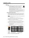
The captive screw audio connector can easily be inadvertently plugged
partially into one receptacle and partially into an adjacent receptacle. This
misconnection could damage the audio circuits. Ensure that the connector
is plugged fully and only into the desired input or output.
N
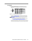
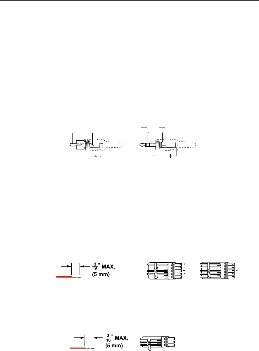
The length of exposed wires is critical. The ideal length is 3/16 inch (5 mm).
• If the stripped section of wire is longer than 3/16 inch, the exposed wires may
touch, causing a short circuit between them.
• If the stripped section of wire is shorter than 3/16 inch, wires can be easily
pulled out even if tightly fastened by the captive screws.
N
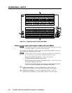
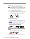
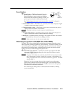
See figure 2-5 to identify the tip, ring, and sleeve when you are making
connections for the switcher from existing audio cables. A mono audio connector
consists of the tip and sleeve. A stereo audio connector consists of the tip, ring
and sleeve. The ring, tip, and sleeve wires are also shown on the captive screw
audio connector diagrams: figure 2-3, figure 2-4, figure 2-6, and figure 2-7.
Tip (+)
Sleeve ( )
Sleeve ( )
Ring (
-
)
Tip (+)
RCA Connector
3.5 mm Stereo Plug Connector
(balanced)
Figure 2-5 — Typical audio connectors
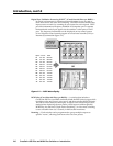
The audio level for each input can be individually set via the front panel or
via Ethernet or RS-232/RS-422 control to ensure that the level on the output
does not vary from input to input. See chapter 3, "Operation", chapter 4,
"Programmer's Guide", chapter 5, "Matrix Software", and chapter 6, "HTML
Operation" for details.
e
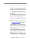
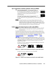
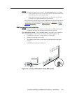
Connections for balanced and unbalanced audio outputs — These 3.5 mm,
5-pole (stereo audio BMEs) or 3-pole (mono audio BMEs) captive screw
connectors output the selected unamplified, line level audio. Connect audio
devices, such as an audio amplifier or powered speakers.
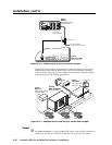
See figure 2-6 to properly wire an output connector for the stereo audio BME.
Unbalanced Stereo Output Balanced Stereo Output
L R
Do not tin the wires!
Ring
Sleeve(s)
Tip
Tip
Ring
Sleeve(s)
Tip
Tip
NO GROUND HERE.
NO GROUND HERE.
Figure 2-6 — Captive screw connector wiring for stereo audio outputs
C
For unbalanced audio, connect the sleeve(s) to the ground contact. DO
NOT
connect the sleeve(s) to the negative (-) contacts).
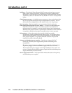
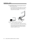
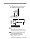
See figure 2-7 to properly wire an output connector for the mono audio BME.
Tip
Ring
Sleeves
Do not tin the wires!
Figure 2-7 — Captive screw connector wiring for mono audio outputs