


CrossPoint 450 Plus and MAV Plus Switchers • Installation
2-2
Installation
Setup and Installation Checklist
Get ready
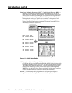
c Familiarize yourself with the CrossPoint 450 Plus and MAV Plus matrix
switcher BMEs.
c Obtain IP setting information for the matrix switcher from the local network
administrator. Read appendix A, “Ethernet Connection”.
Perform physical installation
c If desired, create button labels (page 5-25) and replace them (page B-14).
c
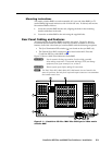
If desired, install the switcher BMEs in a rack (below).
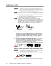
c Set the BME addresses.
c
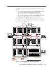
Connect the BME COMM interconnecting cables.
c
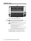
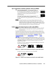
Cable input and output devices to the I/O ports (page 2-4).
c
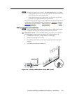
If desired, connect the serial cable(s) to BME 0’s Remote RS-232/RS-422 port
(page 2-9) or front panel Configuration port (page 2-13) and to the PC or
control system.
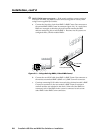
c
If desired, connect an RJ-45 cable between BME 0's LAN port and to a PC or
control system (page 2-10).
c
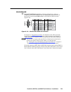
If desired, set the sync termination switches (page 2-5).
c
Connect the AC power cables to all BMEs (page 2-12). Apply AC power to the
BMEs and verify the BMEs power up normally.
c
Test the switcher by creating a tie (page 3-14).
Ancillary operations
c Install the Windows-based control program (page 5-2).
Mounting the Switcher
UL guidelines
The following Underwriters Laboratories (UL) guidelines pertain to the installation
of the matrix switcher BME into a rack.
1
. Elevated operating ambient temperature — If the equipment installed in a
closed or multi-unit rack assembly, the operating ambient temperature of the
rack environment may be greater than room ambient temperature. Therefore,
install the matrix switcher in an environment compatible with the maximum
ambient temperature (TMA = 158 °F , +70 °C) specified by Extron.
2
. Reduced air flow — Install the equipment in a rack so that the amount of air
flow required for safe operation of the equipment is not compromised.
3
. Mechanical loading — Mount the equipment in the rack so that a hazardous
condition is not achieved due to uneven mechanical loading.
4
. Circuit overloading — Connect the equipment to the supply circuit and
consider the effect that circuit overloading might have on overcurrent
protection and supply wiring. Appropriate consideration of equipment
nameplate ratings should be used when addressing this concern.
5
. Reliable earthing (grounding) — Maintain reliable grounding of rack-
mounted equipment. Pay particular attention to supply connections other
than direct connections to the branch circuit (for example, use of power strips).