


Installation, cont’d
CrossPoint 450 Plus and MAV Plus Switchers • Installation
2-10
Ethernet
i
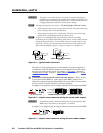
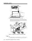
Ethernet port — If desired, for IP control of the system, connect
the matrix switcher to a PC or to an Ethernet LAN via this RJ-45
connector on BME 0 only. You can use a PC to control the
networked switcher with SIS commands from anywhere in the
world. You can also control the switcher from a PC that either is
running the Extron Windows-based control program or that has
downloaded HTML pages from the switcher.
Ethernet connection indicators — The Link and Act LEDs indicate the status
of the Ethernet connection. The Link LED indicates that the switcher is
properly connected to an Ethernet LAN. This LED should light steadily. The
Act LED indicates transmission of data packets on the RJ-45 connector. This
LED should flicker as the switcher communicates.
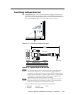
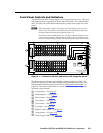
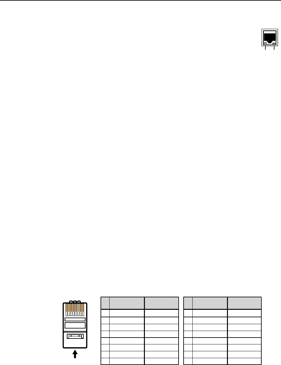
Cabling and RJ-45 connector wiring
It is vital that your Ethernet cables be the correct cables, and that they be properly
terminated with the correct pinout. Fast Ethernet links use Category (CAT) 5e
or CAT 6, unshielded twisted pair (UTP) or shielded twisted pair (STP) cables,
terminated with RJ-45 connectors. Ethernet cables are limited to a length 328 feet
(100 m).
N
Do not use standard telephone cables. Telephone cables do not support Ethernet
or Fast Ethernet.
Do not stretch or bend cables. Transmission errors can occur.
The cable used depends on your network speed. The switcher supports both
10 Mbps (10Base-T — Ethernet) and 100 Mbps (100Base-T — Fast Ethernet),
half-duplex and full-duplex Ethernet connections.
• 10Base-T Ethernet requires CAT 3 UTP or STP cable at minimum.
• 100Base-T Fast Ethernet requires CAT 5e UTP or STP cable at minimum.
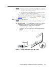
The Ethernet cable can be terminated as a straight-through cable or a crossover
cable and must be properly terminated for your application (figure 2-11).
• Crossover cable — Direct connection between the computer and the
matrix switcher BME 0
• Patch (straight) cable — Connection of the matrix switcher BME 0 to an
Ethernet LAN
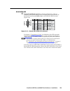
A cable that is wired as T568A at one end
and T568B at the other (Tx and Rx pairs
reversed) is a "crossover" cable.
A cable wired the same at both ends is
called a "straight-through" cable, because
no pin/pair assignments are swapped.
12345678
RJ-45
Connector
Insert Twisted
Pair Wires
Pins:
Crossover Cable Straight-through Cable
Pin
1
2
3
4
5
6
7
8
Wire color
White-green
Green
White-orange
Blue
White-blue
Orange
White-brown
Brown
Wire color
T568A T568B
End 1 End 2 End 1 End 2
White-orange
Orange
White-green
Blue
White-blue
Green
White-brown
Brown
Pin
1
2
3
4
5
6
7
8
Wire color
White-orange
White-green
Blue
White-blue
White-brown
Brown
Wire color
T568BT568B
White-orange
OrangeOrange
White-green
Blue
White-blue
GreenGreen
White-brown
Brown
Figure 2-11 — RJ-45 connector and pinout tables
Link
LED
Activity
LED