


Chapter 6 - Parameter Description [I/O]
6-37
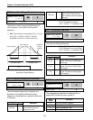
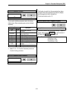
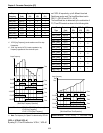
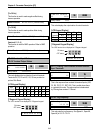
The following table shows the selection in I/O-48.
Setting Range
LCD 7-Seg
Description
None
0
Continuous operating after loss of
frequency reference.
FreeRun
1
Inverter cuts off its output after
determining loss of frequency reference.
Stop
2
Inverter stops by its Decel pattern and
Decel time after determining loss of
frequency reference.
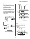
I/O-49 [Time out] sets the waiting time before determining
the loss of reference signal. Inverter waits to determine the
loss of a reference signal until times out.
☞
Note: I/O-48 and I/O-49 also apply when DRV-04 is set to
‘Keypad-1’ or ‘Keypad-2’ for determining the loss of
command frequency.
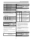
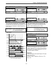
I/O-12: Multi-function Input Terminal ‘P1’ Define
I/O-13: Multi-function Input Terminal ‘P2’ Define
I/O-14: Multi-function Input Terminal ‘P3’ Define
Multi-function input terminals can be defined for many
different applications. The following table shows the
various definitions for them.
Setting Range
LCD 7-Seg
Description
Speed-L
0
Multi-step speed - Low
Speed-M
1
Multi-step speed - Mid
Speed-H
2
Multi-step speed - High
XCEL-L
3
Multi-accel/decel - Low
XCEL-M
4
Multi-accel/decel - Mid
XCEL-H
5
Multi-accel/decel - High
Dc-brake
6
DC injection braking during stop
2nd
Func
7
Exchange to 2
nd
functions
Exchange
8
Exchange to commercial power line
-Reserved-
9
Reserved for future use
Up
10
Up drive
Down
11
Down drive
3-Wire
12
3 wire operation
Ext Trip-A
13
External trip A
Ext Trip-B
14
External trip B
iTerm Clear
15
Used for PID control
Open-loop
16
Exchange between PID mode and
V/F mode
Main-drive
17
Exchange between Option and
Inverter
Analog hold
18
Hold the analog input signal
XCEL stop
19
Disable accel and decel
P Gain2
20
Used for PID control
SEQ-L
21
Sequence operation - Low
SEQ-M
22
Sequence operation - Mid
SEQ-H
23
Sequence operation - High
Manual
24
Exchange between Sequence
operation and Manual operation
Go step
25
Triggering Sequence operation
(Auto-B)
Hold step
26
Hold last step (Auto-A)
Trv Off.Lo
27
Trv Off.Hi
28
Used for Traverse Operation
Interlock1
29
Interlock2
30
Interlock3
31
Interlock4
32
Used for MMC operation
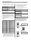
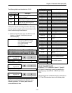
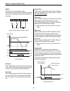
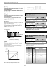
[Speed-L, Speed-M, Speed-H]
By setting P1, P2, P3 terminals to ‘Speed-L’, ‘Speed-M’
and ‘Speed-H’ respectively, inverter can operate at the
preset frequency set in DRV-05 ~ DRV-07 and I/O-20 ~
I/O-24.
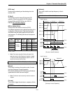
The step frequencies are determined by the combination of
P1, P2 and P3 terminals as shown in the following table.
Related Functions: DRV-04 [Frequency Mode]
I/O-02 [V1 Input Minimum Voltage]
I/O-07 [I Input Minimum Current]
I/O-48 [Lost command]
I/O-49
[
Time out
]
I/O►
P1 dedine
12 Speed-L
0 12
Factory Default: Speed-L 0
I/O►
P2 dedine
13 Speed-M
1 13
Factory Default: Speed-M 1
I/O►
P3 dedine
14 Speed-H
2 14
Factory Default: Speed-H 2
2 14