


Chapter 1 - Installation
1-7
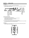
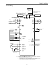
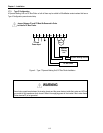
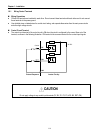
1.6 Basic Wiring
2
30/460 V
50/60 Hz
U
V
W
G ( )
R
S
T
N
1
DB Unit(Optional)
4
DB Resitor
φ
3
MCCB(OPTION)
FX
RX
BX
RST
P1
P3
CM
VR
V1
I
5G
+
FM
5G
(N.O.)
A
AXA
AXB
Output Frequency Meter
(0~10V Linear)
P2
MOTO
R
Potentiometer
(1 kohm, 1/2W)
Speed signal Input
2
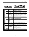
Forward Run/Stop
Reverse Run/Stop
Inverter Disable
Fault Reset
Multi-function Input 1
Multi-function Input 2
Multi-function Input 3
Common Terminal
Factory Setting:
‘Speed-L’
‘Speed-M’
‘Speed-H’
Power suppl
y
for
speed signal:
+ 11V, 10mA
Speed signal input:
0 ~ 10V
Speed signal input:
4 ~20mA (250ohm)
Common for
VR, V1, I
Fault output relay
lless than AC250V, 1A
lless than DC30V, 1A
Multi-function output relay1
lless than AC250V, 1A
lless than DC30V, 1A
Factory setting: ‘Run’
Note) Main Circuit Terminals Control Circuit Terminals.
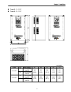
1. The terminal configuration varies depend on the model number. Please refer to the ‘1.7 Power terminals’.
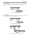
2. Analog speed command may be set by Voltage, Current or both.
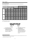
3. When installing the DC Reactor, the Common Busbar between P1 and P2 must be removed.
4. 1 ~ 10 HP inverters have on-board braking circuit. Braking resistors are only included for 1 ~ 5 inverters.
15 ~ 30 HP inverters need optional braking unit and resistor for dynamic braking.
P2
1
P1
1
DC Bus Choke (Optional)
3
FM
Dynamic
Braking Unit
(Optional)
P N B1 B2
DC Bus Choke DB Resistor
JOG
Jog
Shield
(N.C.) B
C