Chapter 6 - Parameter Description [EXT]
6-57
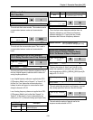
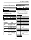
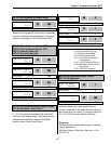
EXT-24: Slip Frequency for ‘Sub-B’ Board
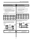
This is the limit frequency the inverter uses to compensate
the motor speed drop due to load fluctuation. The set point
value is the percentage of FUN-32 [Rated Motor Slip].
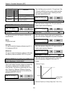
EXT-25: P Gain for Sensored Vector_SPD
EXT-25: I Gain for Sensored Vector_SPD
EXT-27: Forward Torque Limit
EXT-28: Reverse Torque Limit
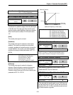
EXT-30 ~ EXT-32: Multi-Function Output Terminal
(Q1, Q2, Q3) Define – Sub-A, Sub-C
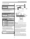
Q1, Q2, Q3 terminals are provided on Sub-A and Sub-C
board as an open collector output. The functions of these
terminals can be selected the same as I/O-44 [Multi-
function Auxiliary Contact Output Define].
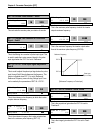
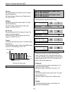
EXT-34: LM (Load Meter) Output – Sub-A
EXT-35: LM Adjustment
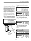
Load meter displays the inverter output Frequency,
Current, Voltage and DC link voltage with pulse signals on
the LM terminal of Sub-A board. The average ranges from
0V to 10V. EXT-35 is used to adjust the LM value.
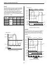
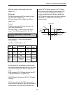
[Frequency]
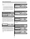
LM terminal outputs inverter output frequency. The output
value is determined by,
LM Output Voltage = (Output freq. / Max. freq.) × 10V ×
EXT-35 / 100
EXT►
PG Slip Freq
24 100 %
100 24
Factory Default: 100 % 100
EXT►
Q1 define
30 FDT-1
0 30
Factory Default: FDT-1 0
EXT►
Q2 define
31 FDT-2
1 31
Factory Default: FDT-2 1
EXT►
Q3 define
32 FDT-3
2 32
Factory Default: FDT-3 2
EXT►
LM mode
34 Current
1 34
Factory Default: Current 1
EXT►
LM Adjust
35 100 %
100 35
Factory Default: 100 % 100
Related Functions: FU1-54 [Overload Warning Level]
FU1-55 [Overload Warning Time]
FU1-59 [Stall Prevention Mode]
FU1-60 [Stall Prevention Level]
I/O-12 ~ I/O-14 [Multi-function Input
Terminal define]
I/O-42 ~ I/O-43 [Frequency Detection]
I/O-44 [Multi-function Auxiliary Contact
Output define]
I/O-50 ~ I/O-56 [Auto Operation]
EXT►
ASR P-gain
25 100 %
150 25
Factory Default: 150 % 150
EXT►
ASR I-gain
26 200 ms
200 26
Factory Default: 200 ms 200
EXT►
TRQ + Limit
27 100 %
150 27
Factory Default: 150 % 150
EXT►
TRQ – Limit
28 100 %
150 28
Factory Default: 150 % 150


