


Chapter 6 - Parameter Description [APP]
6-63
motors including main motor. For mode ‘2’, external
sequence (Refer to APP-26) should be configured.
♦ Abnormal motor can be skipped from running by using
the multi-function input terminals (P1, P2, P3, and P4). If a
multi-function terminal is opened, the inverter stops all
running motors and restarts operation with only normal
motors except the abnormal motor. (Refer to APP-29)
♦ Sleep function is initiated when flow demand is low.
Inverter stops motor when the motor runs below Sleep
Frequency (APP-24) during Sleep Delay Time (APP-23).
While in the sleep state, inverter keeps monitoring and
initiates Wake-Up function when the real value of the
controlling amount has decreased below the Wake-Up
level (APP-25).
☞
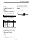
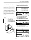
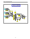
Note: Only one auxiliary motor can be connected with AUX
terminal on control terminal strip without using MMC Option
Board.
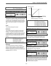
[MMC Diagram]
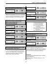
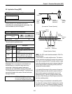
[Draw]: This is a kind of Open-Loop Tension Control. This
is used to maintain constant tension of material with the
speed difference between main motor and subordinate
motor.
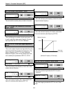
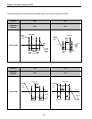
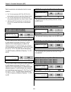
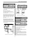
APP-02: Traverse Amplitude
This code sets the frequency amplitude of traverse
operation. The value is the percentage of reference
frequency. The output value is determined by,
Trv. Amp Frequency = (Reference Freq. * Trv. Amp)/100
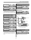
APP-03: Traverse Scramble Amplitude
This code sets the frequency amplitude of scramble
operation. The output value is determined by,
Trv. Scr Frequency = (Trv. Amp Frequency * (100 - Trv.
Scr))/100
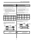
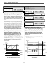
APP-04: Traverse Accel Time
APP-05: Traverse Decel Time
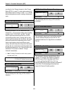
APP►Trv. Amp[%]
02 0.0%
0.0 02
Factory Default: 0.0% 0.0
APP►Trv. Scr[%]
03 0.0%
0.0 03
Factory Default: 0.0% 0.0
APP►Trv Acc Time
04 2.0 sec
2.0 04
Factory Default: 2.0 sec 2.0
APP►Trv Dec Time
05 3.0 sec
3.0 05
Factory Default: 3.0 sec 3.0
Related Functions:
A
PP-08 to APP-31 [MMC Parameters]
DRV-04 [Frequency Mode]
FU2-47 [PID Operation Selection]
I/O-01 to I/O-10 [Analog Signal Input]
EXT 15 to EXT21 [Pulse Input Signal]
I/O-12 to I/O-14 [Multi-Function Input]
EXT-30 to EXT-32 [Multi-Function Output]
Related Functions:
A
PP-32 to APP-33 [Draw Parameters]
DRV-04 [Frequency Mode]
I/O-01 to I/O-10 [Analog Signal Input]
EXT 06 to EXT-10 [Analog Input Setting]
I/O-12 to I/O-14 [Multi-Function Input]
EXT-02 to EXT-04 [Multi-Function Input]
V1
V2
I
M1
M2
M3
M4
M
ACti
M
Input
Power
Main Motor
A
ux. Motor 4
A
ux. Motor 3
Aux. Motor 2
Aux. Motor 1
MMC Board
AUX
RLY1
RLY2
RLY3