


Chapter 6 - Parameter Description [DRV]
6-6
☞ Note: The frequency setting method of ‘Speed 0’ is decided
by DRV-04.
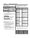
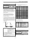
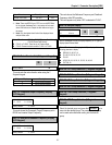
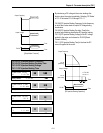
DRV-08: Output Current
This code displays the output current of the inverter in
RMS.
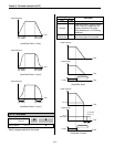
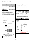
DRV-09: Motor Speed
This code displays the motor speed in RPM while the
motor is running.
Use the following equation to scale the mechanical speed
using FU2-74 [Gain for Motor Speed display] if you want to
change the motor speed display to rotation speed (r/min)
or mechanical speed (m/min).
Motor speed = 120 * (F/P) * FU2-74
Where, F= Output Frequency and P= the Number of Motor Poles
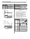
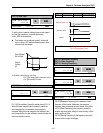
DRV-10: DC Link Voltage
This code displays the DC link voltage inside the inverter.
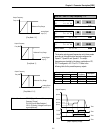
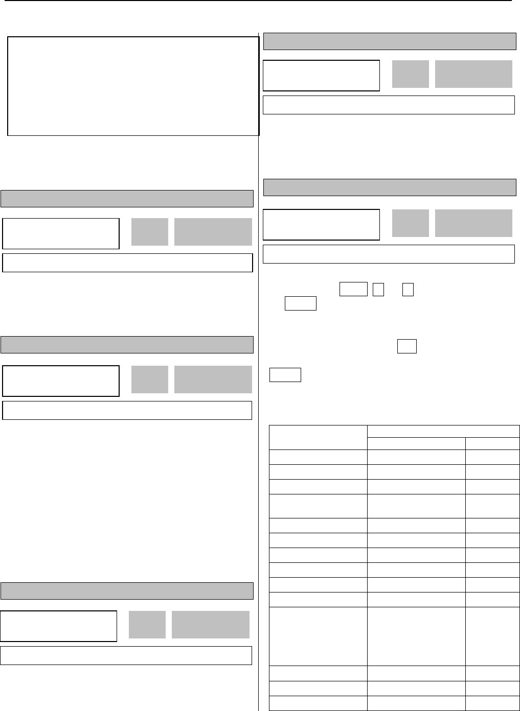
DRV-11: User Display Selection
This code displays the parameter selected in FU2-73 [User
Display]. There are types of parameters in FU2-73:
Voltage, Watt and Torque.
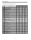
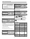
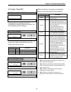
DRV-12: Fault Display
This code displays the current fault (trip) status of the
inverter. Use the PROG,
▲ and ▼ key before pressing
the RESET key to check the fault content(s), output
frequency, output current, and whether the inverter was
accelerating, decelerating, or in constant speed at the time
of the fault occurred. Press the ENT key to exit. The fault
content will be stored in FU2-01 to FU2-05 when the
RESET key is pressed. For more detail, please refer to
Chapter 7.
[Fault Contents]
Keypad display
Fault (Trip)
LCD 7-Segment
Over-Current 1 Over Current 1
OC
Over-Voltage Over Voltage
OV
External Trip Input A External-A
EXTA
Emergency Stop
(Not Latched)
BX
BX
Low-Voltage Low Voltage
LV
Fuse Open Fuse Open
FUSE
Ground Fault Ground Fault
GF
Over-Heat on Heat sink Over Heat
OH
Electronic Thermal Trip E-Thermal
ETH
Over-Load Trip Over Load
OLT
Inverter H/W Fault
- EEP Error
- ADC Offset
- WDOG Error
- In-Phase Open
HW-Diag
HW
External Trip Input B
External-B
EXTB
Over-Current 2
Arm Short
ASHT
Option Error
Option
OPT
DRV
►
Current
08 0.0 A
0.0 08
Factory Default: 0.0 A 0.0
DRV
►
Speed
09 0rpm
0 09
Factory Default: 0rmp 0
Related Functions: I/O-12 to I/O-14 [Reference Inputs]
I/O-17 [Filtering Time Constant]
I/O-21 to I/O-21 [Step Frequency 4~7]
I/O-01 to I/O-10: Scaling the analog input signals (V1 and I)
for frequency reference.
I/O-17: Adjusts the response sensibility of the input terminal
to eliminate contact noise.
I/O-21 to I/O-24: Sets the step frequency from 4 to 7.
DRV
►
DC link vtg
10 ----- V
----
10
Factory Default: ---- V ----
DRV
►
User disp
11 Out 0.0 V
0.0 11
Factory Default: 0.0 V 0.0
DRV
►
Fault
12 None
nOn 12
Factory Default: None nOn