


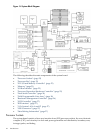
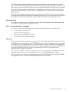

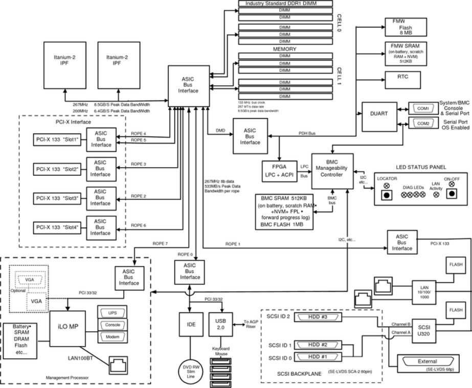
Figure 1-4 System Block Diagram
The following describes the main components of the system board:
• “Processor Sockets” (page 22)
• “Processor Bus” (page 23)
• “ZX1 I/O and Memory Controller” (page 23)
• “Memory” (page 23)
• “I/O Bus Interface” (page 25)
• “Processor Dependent Hardware Controller” (page 25)
• “Dual Serial Controller” (page 26)
• “Field Programmable Gate Array” (page 26)
• “Baseboard Management Controller” (page 26)
• “SCSI Controller” (page 27)
• “IDE Interface” (page 27)
• “1 Gb System LANs A and B” (page 27)
• “USB Connectors” (page 27)
• “Data Pathing Information” (page 27)
Processor Sockets
The system board consists of two zero insertion force (ZIF) processor sockets, the core electronic
complex (CEC), and circuitry for clock and power generation and distribution, boundary scan,
in-target probe, and debug.
22 Introduction