


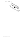
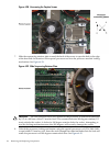
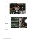
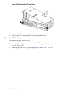
Figure 4-35 Locking the Processor Module in Place
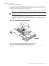
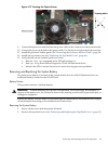
7. Slide the sequencing retainer plate toward the rear of the server.
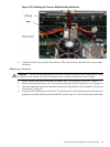
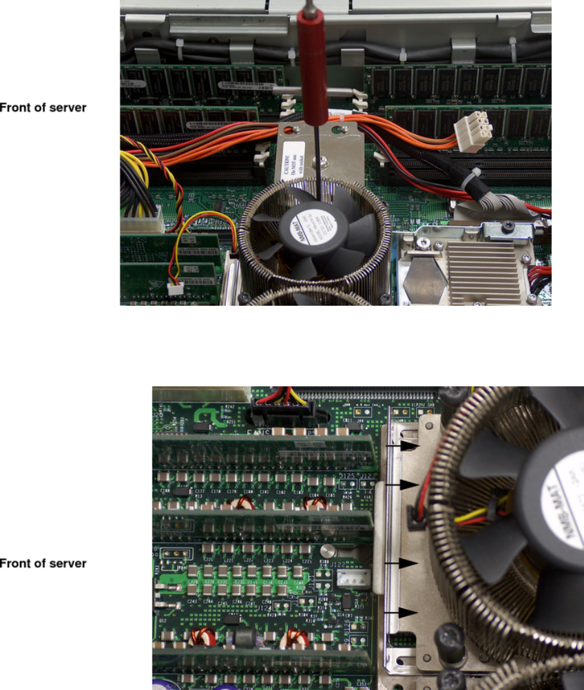
Figure 4-36 Sliding the Sequencing Retainer Plate
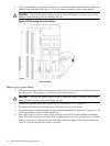
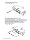
8. Install the four processor captive screws, and the two heat sink captive screws in the order
shown here.
68 Removing and Replacing Components