182 Technical Reference
Configuration Switches
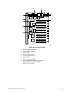
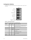
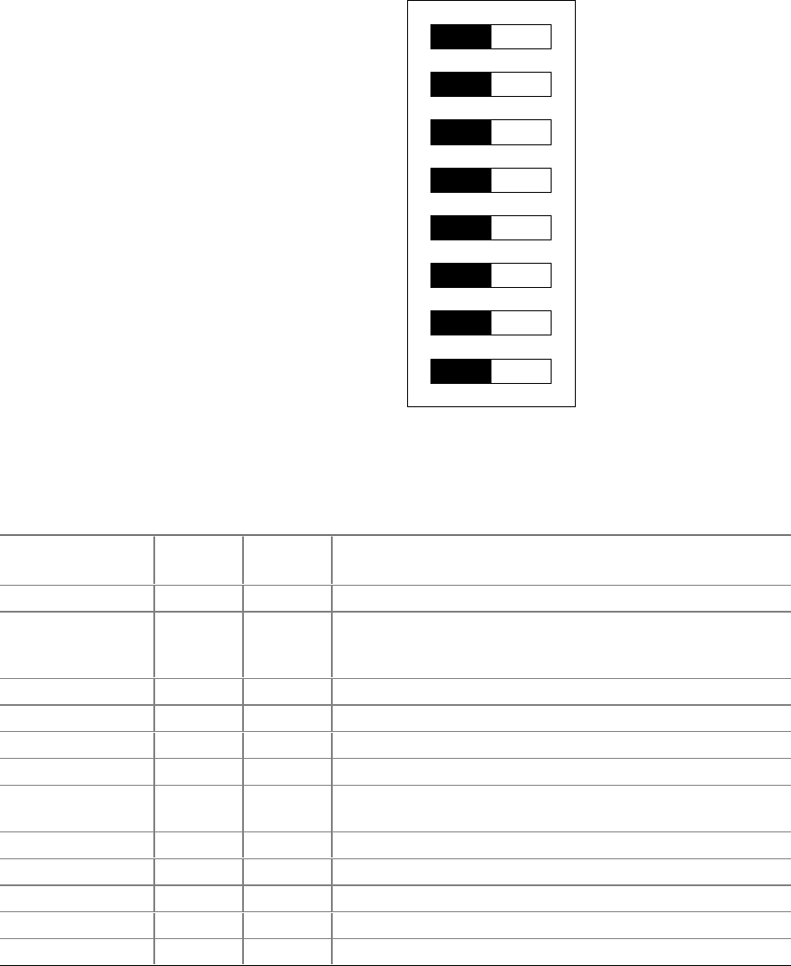
One header provides eight switches that control various configuration options. Figure 57 shows
the switches.
SW4G1
8
7
6
5
4
3
2
1
Reserved
Recovery Boot
Spare
BIOS Write Enable
Clear CMOS
Password Clear
PHP Override
Reserved
Figure 57. I/O Carrier Configuration Switches
Table 29. I/O Carrier Switch Summary
Items in bold show default placement for each configurable option.
Function
Switch
Number
Default
Setting What it does at system reset
Reserved 1
Disabled
N/A
Recovery Boot 2 Enabled BIOS attempts a recovery boot, loading BIOS code from a
diskette into the flash device. This is typically used when
BIOS code has been corrupted.
Disabled
System attempts to boot using BIOS stored in flash memory.
Spare (Reserved) 3
Disabled
N/A
BIOS Update 4 Disabled No BIOS flash update allowed.
Enabled
Allow BIOS flash update.
CMOS Clear 5 Enabled Replaces the contents of NVRAM with the manufacturing
default settings.
Disabled
Preserves the contents of NVRAM.
Password Clear 6 Enabled Clears the current system password.
Disabled
Maintains the password.
PHP Override 7
Disabled
N/A
Reserved 8
Disabled
N/A


