


Chapter 2: Installing the Hardware
5536 PRI RAS Communications Controller Users Guide 23
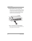
For optimal electrical signal quality on the MVIP ribbon cable,
you must place the MVIP boards in a specific order (depending
on the number of connections) and electrically terminate two
MVIP clock signals, as described in the following topics.
MVIP Electrical Termination Requirements
For systems with five or fewer MVIP Bus connections and less
than 90 pF load on the clock lines, it is adequate to do the
following:
1. Place the circuit board that is the master clock source at
one end of the cable.
2. Electrically terminate the MVIP Bus only on the circuit
board located at the other end of the cable.
NOTE
An 5536 board is generally the master clock source
because it is connected to the network. In this case, place
an 5536 board at one end of the cable, and do not
electrically terminate the bus on this board.
On systems with more than five MVIP Bus connections or
more than 90 pF of load on the clock lines, both ends of the
cable must be electrically terminated. No other boards should
be electrically terminated.