


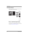

Connector Pinouts
34 Interphase Corporation
Connector Pinouts
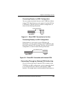
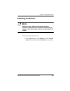
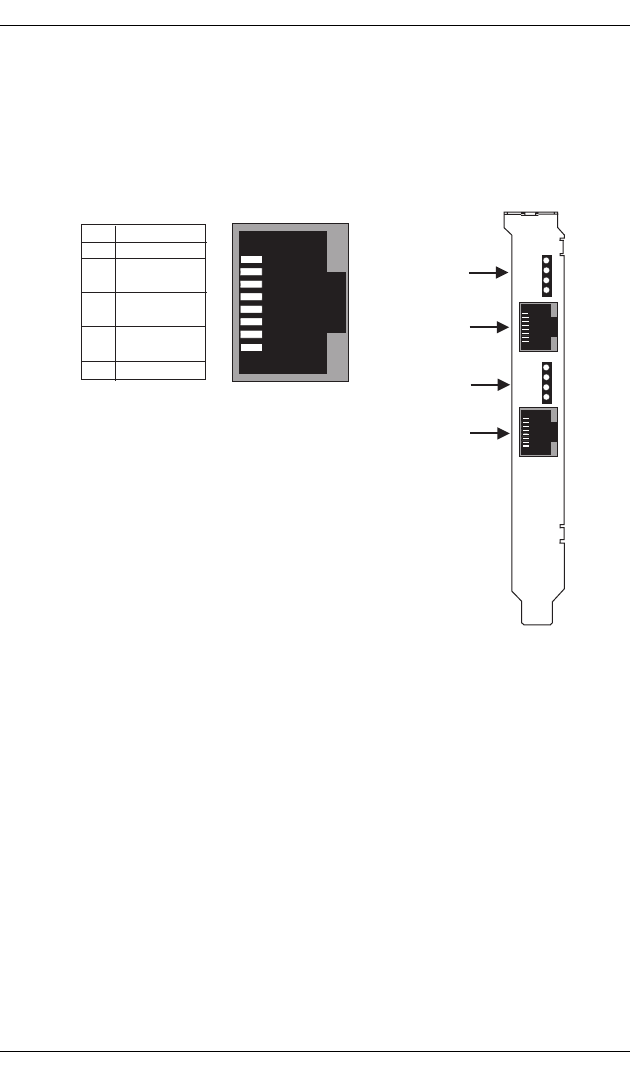
The following illustration of the board’s faceplate shows the
board’s connectors and connector pins:
Figure 3-5. Faceplate and Connector Pinouts
The board’s connectors follow the RJ48C specification.
For each connector, four LEDs display the status of the link (as
described in Interpreting LEDs on page 118).
1
2
3
4
5
6
7
8
Pin
Tx out (tip)
Tx out (ring)
Rx in (ring)
Rx in (tip)
Signal
8
1
(RJ48C)
(RJ48C)
Port #1
(Port #1)
(Port #0)
Port #0
LEDs 5, 6, 7 & 8
LEDs 1, 2, 3 & 4
RJ48C Pinout