


Connecting to an MVIP Bus
24 Interphase Corporation
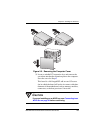
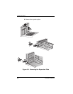
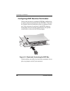
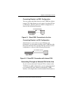
Configuring MVIP Electrical Termination
If this is the last board in a multiple MVIP Bus configuration,
it requires electrical termination in the MVIP Bus. To provide
the required electrical termination, place two jumpers on the
two 2-pin connectors located next to the MVIP connector.
Each jumper must be inserted perpendicular to the printed
circuit board, as shown in the following figure:
Figure 2-5. Electrically Terminating the MVIP Bus
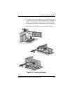
If the board does not need to be electrically terminated, do not
place any jumpers on the 2-pin connectors.