


Chapter 2: Installing the Hardware
5536 PRI RAS Communications Controller Users Guide 25
Modem Connection LEDs
The 5536-DM RAS provides an LED for each modem
included on the board (for example, 12 LEDs for 12 modems).
These LEDs turn on when a modem has established a
connection on the MVIP Bus. They turn off when the modem
has interrupted the connection.
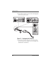
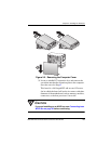
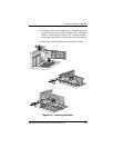
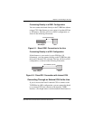
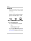
Completing the MVIP Bus Connection
To create a dedicated interconnection among MVIP boards,
connect a ribbon cable to the 40-pin, double-row, right-angled
headers on the top edges of the boards.
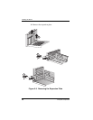
After you finish connecting the board to the MVIP Bus, finish
the remaining steps in the Installing the Board section.