


B.1 Parallel Interface
B-3
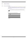
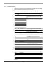
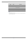
B.1.2 Interface Signals
Table shows the connector pins and corresponding input and output signals of the parallel
interface. Explanation of each signal is also given in the table.
The description in [ ] indicates signal names in Auto mode and Nibble (high) mode (IEEE
1284-compliant). In Auto and Nibble modes, these signals are bidirectional.
Pin In or
out
Signal Description
1 In Strobe
†
[nStrobe] A negative-going-strobe pulse causes the printer to read
and latch the data on the Data 0 [1] to Data 7 [8] signal
lines.
2 In Data 0 [Data 1] These eight signals form one byte of data sent from host
computer to printer. Data 7 [8] is the most significant bit.
3 In Data 1 [Data 2]
4 In Data 2 [Data 3]
5 In Data 3 [Data 4]
6 In Data 4 [Data 5]
7 In Data 5 [Data 6]
8 In Data 6 [Data 7]
9 In Data 7 [Data 8]
10 Out Acknowledge
†
[nAck] This negative-going pulse acknowledges the previous
character received.
11 Out Busy [Busy] When this signal is high, the printer is busy. When it is low,
the printer is able to receive more data.
12 Out Paper Empty
[PError]
This signal goes high when the printer runs out of paper.
††
13 Out Online (Select) [Select] This signal goes high when the printer is online and low
when the printer is offline. The signal goes low when you
press the GO key to make the printer go off line.
††
14 In — [nAutoFd] Ignored
15 —— Not used
16 — 0 V DC
17 — Chassis Ground
18 — +5 V DC This pin is used for the printer’s +5 V DC power supply
(+5±0.5 V, 400 mA maximum, with fuse)
19 — Ground return
20 — Ground return
21 — Ground return
22 — Ground return
23 — Ground return
24 — Ground return
25 — Ground return
26 — Ground return
27 — Ground return
28 — Ground return
29 — Ground return
Table B-2