


B.3 Serial Interface (Option)
B-6
B.3 Serial Interface (Option)
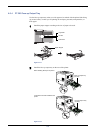
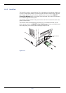
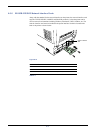
Installing the optional serial interface board kit (IB-11) in the printer enables connection to a
computer with an RS-232C standard serial interface.
B.3.1 Interface Signals
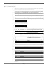
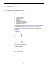
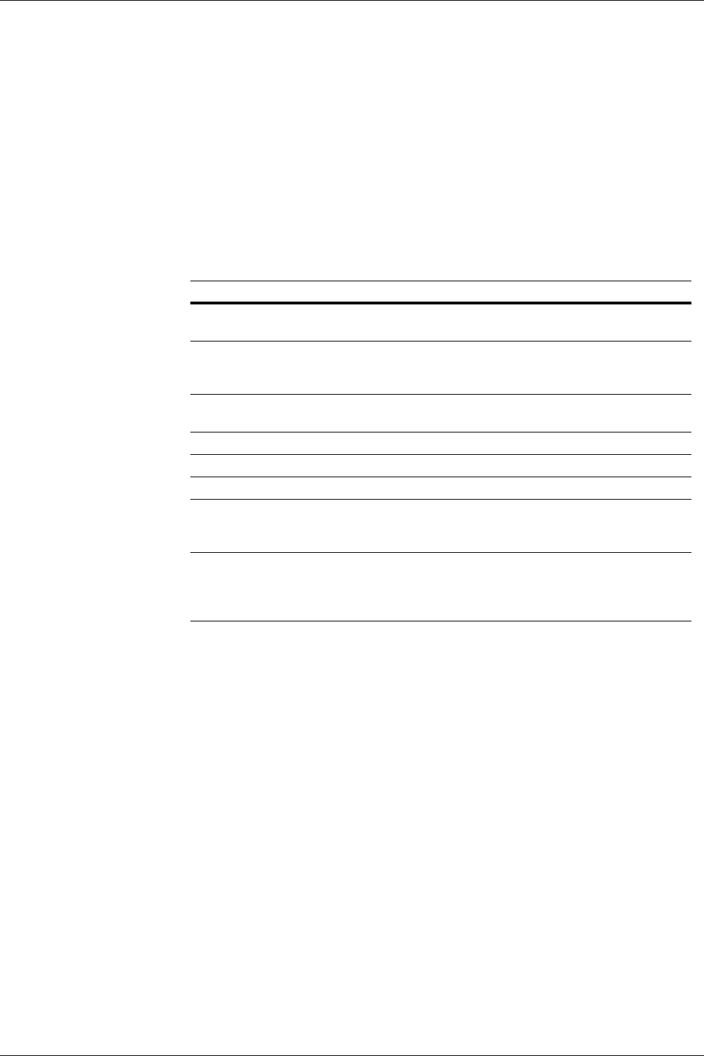
Table B-4 below shows the pins and corresponding input and output signals of the RS-232C
interface connector.
B.3.2 Interface voltage levels
The voltage levels of the interface signals conform to EIA RS-232C specifications. The
voltage level of SPACE is 3 to 15 volts. The voltage level of MARK is -3 to -15 volts.
Voltages between -3 and 3 volts are undefined.
Pin In or out Signal Description
1 — FG Frame Ground. This pin is connected directly to the printer
frame.
2 Out TXD Transmit Data. This pin is used to output asynchronous data
sent from the printer to the computer. This signal is often used
in handshaking.
3 In RXD Receive Data. This pin is used to input serial asynchronous
data sent from the computer to the printer.
4 Out RTS Request To Send. This output is always high (above 3 volts).
5 In CTS Clear To Send. Not used.
6 In DSR Data Set Ready. Not used.
7 — SG Signal Ground. This pin is used to establish a common refer-
ence level for the voltages of all signals other than Frame
Ground.
20 Out DTR Data Terminal Ready . This pin is used to notify the status of
the printer buffer (i.e., nearly full or nearly empty) when hand-
shaking is used. The pin goes high (above 3 volts) when the
buffer is able to accept more data.
Table B-4