


B.5 RS-232C Cable Connection
B-9
B.5 RS-232C Cable Connection
B.5.1 Preparing an RS-232C Cable
After you procure an RS-232C cable, check its wiring against the pin assignments shown in
page section B.1.2 Interface Signals on page B-3. If you have an IBM communications
adapter cable type 1502067, use the procedure below to solder the wiring at the end (printer
side) of the cable:
1
Unscrew the plastic cover at the end (printer side) of the cable.
2
A bare shield wire is provided for each wire in the cable. Solder all shield wires
together into a single bundle.
3
Connect the bundled shield wires to the connector metal face using a piece of flat
cable about 3 mm wide and 15 mm long,. Make sure that the soldered connections
are secure.
4
Unsolder wires 2 and 3, then resolder them in a crossover configuration. In other
words, solder wire 2 to pin 3 and wire 3 to pin 2. Cover the solder joints with a
thermofit tube.
5
Cut wires 4, 5, 6, and 20.
6
Solder wires 5 and 6 together and connect them to pin 20. Cover the solder joints
with a thermofit tube. Leave wire 4 unconnected.
7
Tape all remaining loose ends together, or seal them with a thermofit tube.
8
Screw the plastic cover back on the cable end.
B.5.2 Connecting the Printer to the Computer
Make sure that both computer and printer are powered off.
1
Discharge static electricity from your body by touching a metal object such as a
doorknob.
2
Plug the end (printer side) of the RS-232C cable into the printer’s serial interface
connector and screw it on securely.
3
Plug the other end of the cable into the computer’s serial interface connector.
4
Power on the printer.
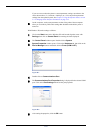
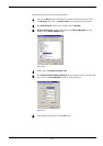
5
The printer’s parameters are set at the factory as follows:
Baud rate = 9600 bps, data bits (character length) = 8, stop bits = 1, parity = none
The two RS-232C protocols are XON/XOFF and DTR. The printer executes both of
these protocols simultaneously, using positive logic for DTR.