2: Overview
Spider™ and SpiderDuo® KVM-over-IP Device User Guide 17
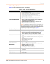
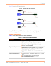
One model with cable length of 21”
One model with cable length of 58”
Secure, full BIOS-level control of remote servers over an IP network
Space–saving “zero footprint” package attaches directly to the server that saves rack space
Flexible 1–port design allows growth
Guaranteed non-blocked access to remote servers that ensures lowest “cost-per-remote user”
Browser–based, no client software or special licensing required
Virtual Media support allows local drive (floppy, CD, hard drive, USB stick) sharing with a
remote server or remote installation of an OS from an .ISO image
Direct KVM minimizes the number of clicks to the remote–server console
Built-in RS-232 serial port that can be configured for serial console pass-through or remote
dial-in access
Ideal for distributed IT system environments such as small branch offices, campuses, test
labs, and server hosting environments
Server-powered design - no external power supply required
Lantronix SwitchPort+ technology allows Spider devices to be cascaded or share a host
Ethernet connection
Functionality
The Spider device captures the video output from the attached computer, compresses and sends
it over the network to a Java KVM console window launched by the browser or to a command line
interface on the user system, which displays a replica of the server video output on the user
monitor.
The Spider device also uses Java KVM coaxnsole to accept keystrokes and mouse movements
on the user system; recognizes those intended for the target computer; transmits the keystrokes
and mouse movements; and emulates a physically attached keyboard and mouse.
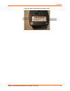
Note: The Spider device supports up to 1600 x 1200 resolution at 60 Hz if its hardware
revision is G22, G23, E21 or higher. If the Spider device hardware is an earlier revision, it
will only support resolutions up to 1280 x 1024 at 60 Hz. The hardware revision number
can be found on the Product Information Label as shown in
Figure 2-8.
System Configuration and Cables
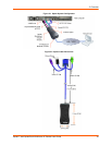
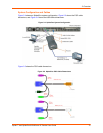
Figure 2-1 shows the Spider system configuration, and Figure 2-2 shows the cable dimensions.


