


Appendix – Re-Assembly Procedure
8
9
0
0
Appendix
Re-Assembly Procedure for 200A /
250A drives
The followings tools are required to properly
reconnect the two cabinets:
− Socket wrench and ratchet with 150mm
(6.0”) extension
− 10mm hex socket
− #2 Phillips screwdriver, 50mm (2.0”) shaft
− #2 Phillips screwdriver, 180mm (7.0”) shaft
− Flat screwdriver, 3mm x 100mm (1/8” x 4”)
− 8mm (5/16”) Allen hex key, any length
− ½” Allen hex key, any length
− 13mm open / box end wrench
The following details the connection
procedure:
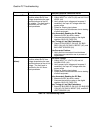
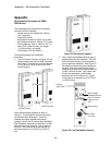
1. The U-Channels, as seen in Figure 18, are
factory bolted onto the Line Side Converter.
Verify the U-Channels are torqued between
1.81-2.26 N-m (16-20 in-lbs) on the Line
Side Enclosure
Figure 1 : Enclosure Connections
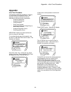
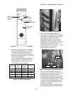
Push cabinets tightly together as seen in
Figure 9. The U-channels will lock into place
on the Motor Side Enclosure. Once the
cabinets are tightly together and placed
correctly, secure the U-channel onto the Motor
Side Enclosure using the provided four (4) M8
bolts with split lock washers. Use an open or
box end 13mm wrench to torque the four (4)
hex cap screws to 1.81-2.26 N-m (16-20 in-
lbs).
Figure 1 : Enclosures Together
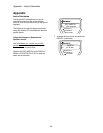
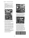
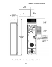
2. Next, install the braided electrical ground
plate between the two cabinets. The Line
Side Converter comes pre-wired with the
ground plate pre-attached. See Figure 2
for details on where the ground plates are
located. Attach the ground plate to the
Motor Side Inverter using the provided four
(4) M5 x 9.5mm screws. Use a 8mm hex
socket with extension, or #2 Phillips
screwdriver with 50-180mm (2-7”) shaft.
Torque these connections to 4.75-5.20 N-
m (42-46 in-lbs).
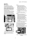
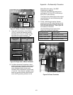
U-Channels
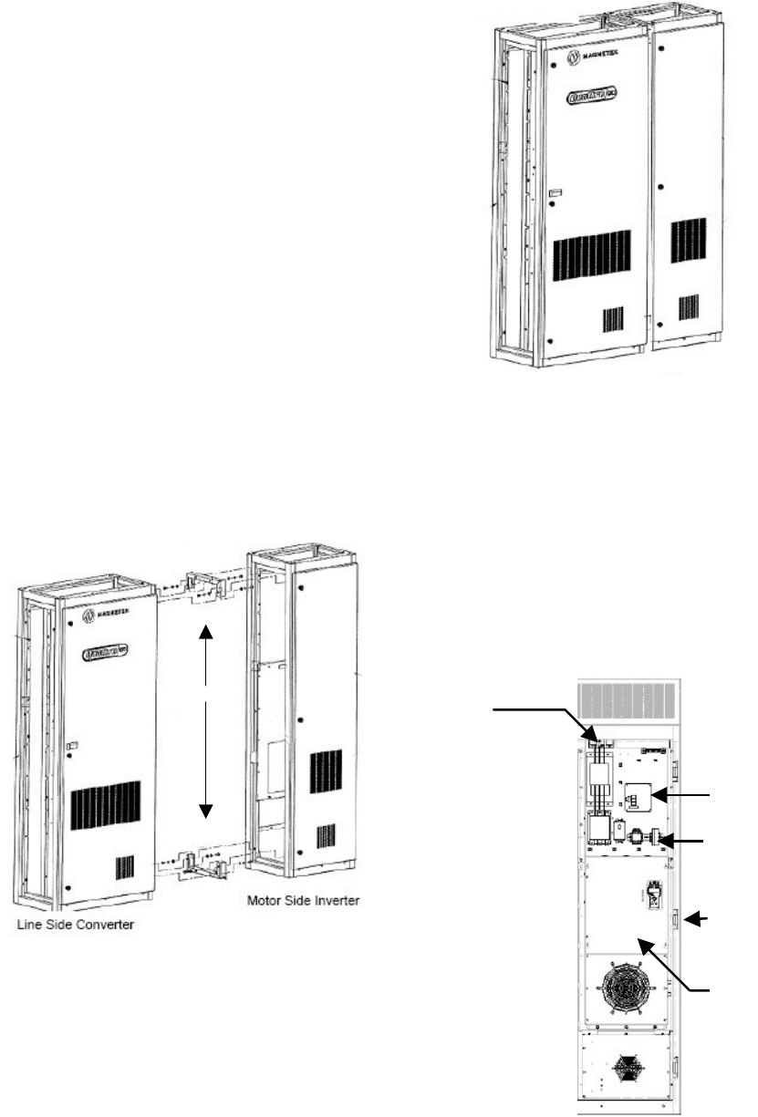
3-Phase
Input Power
Motor Voltage
Feedback Bd (A8)
230 VAC Control
Power Input F1
& F2
Line Side
Converter
Ground Plate
Figure 2 : Line Side Module Position
98